
Extended range digital-to-analog conversion

a digital-to-analog conversion and extended range technology, applied in digital-to-analog convertors, physical parameters compensation/prevention, instruments, etc., can solve the problems of time-varying envelopes, increased out-of-band emissions, and errors in wanted signals, and achieve the effect of reducing the quantization noise produced in the conversion

Inactive Publication Date: 2004-11-23
NORTHROP GRUMMAN SYST CORP
View PDF9 Cites 79 Cited by
  • Summary
  • Abstract
  • Description
  • Claims
  • Application Information

AI Technical Summary

Benefits of technology

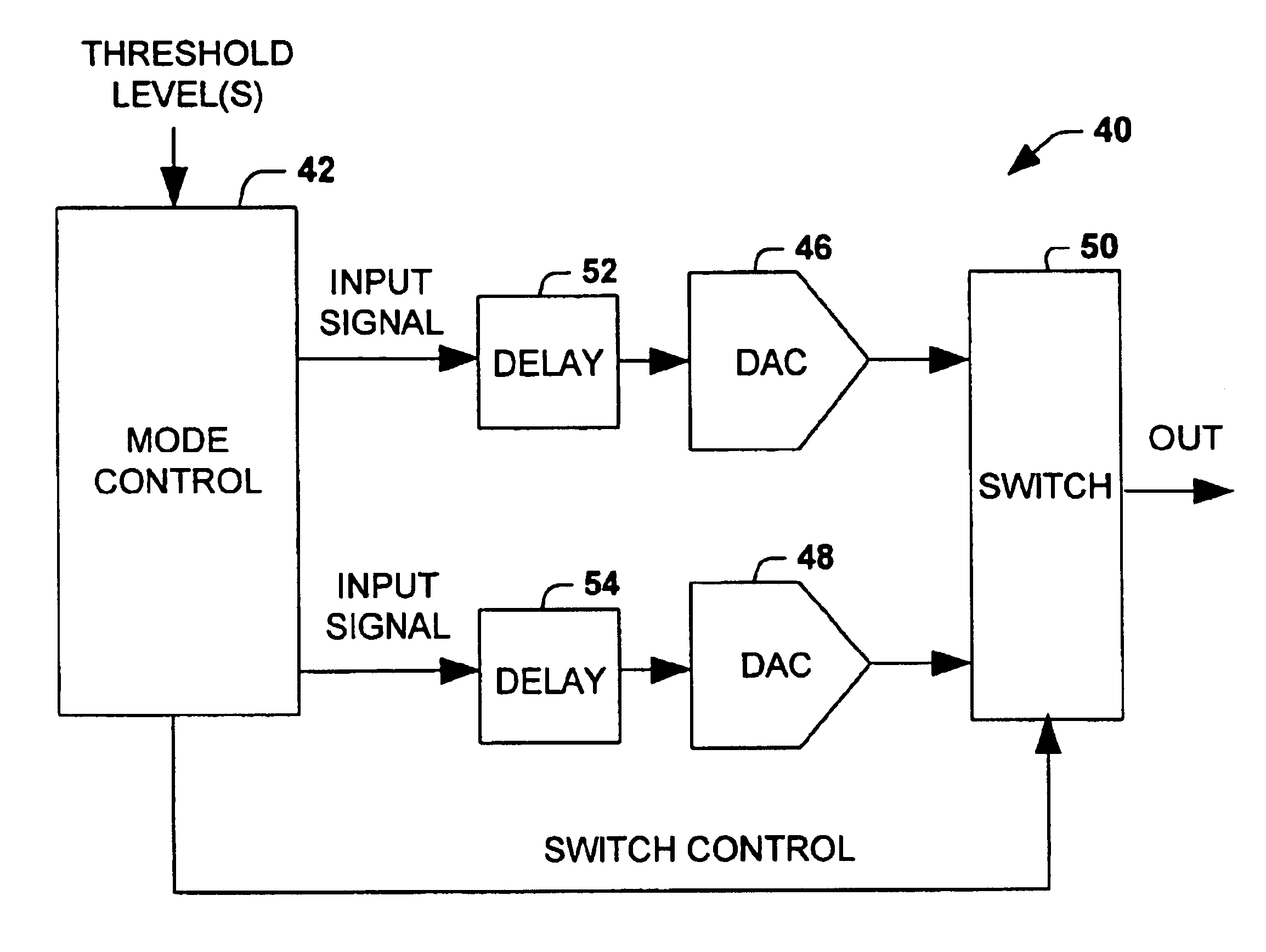
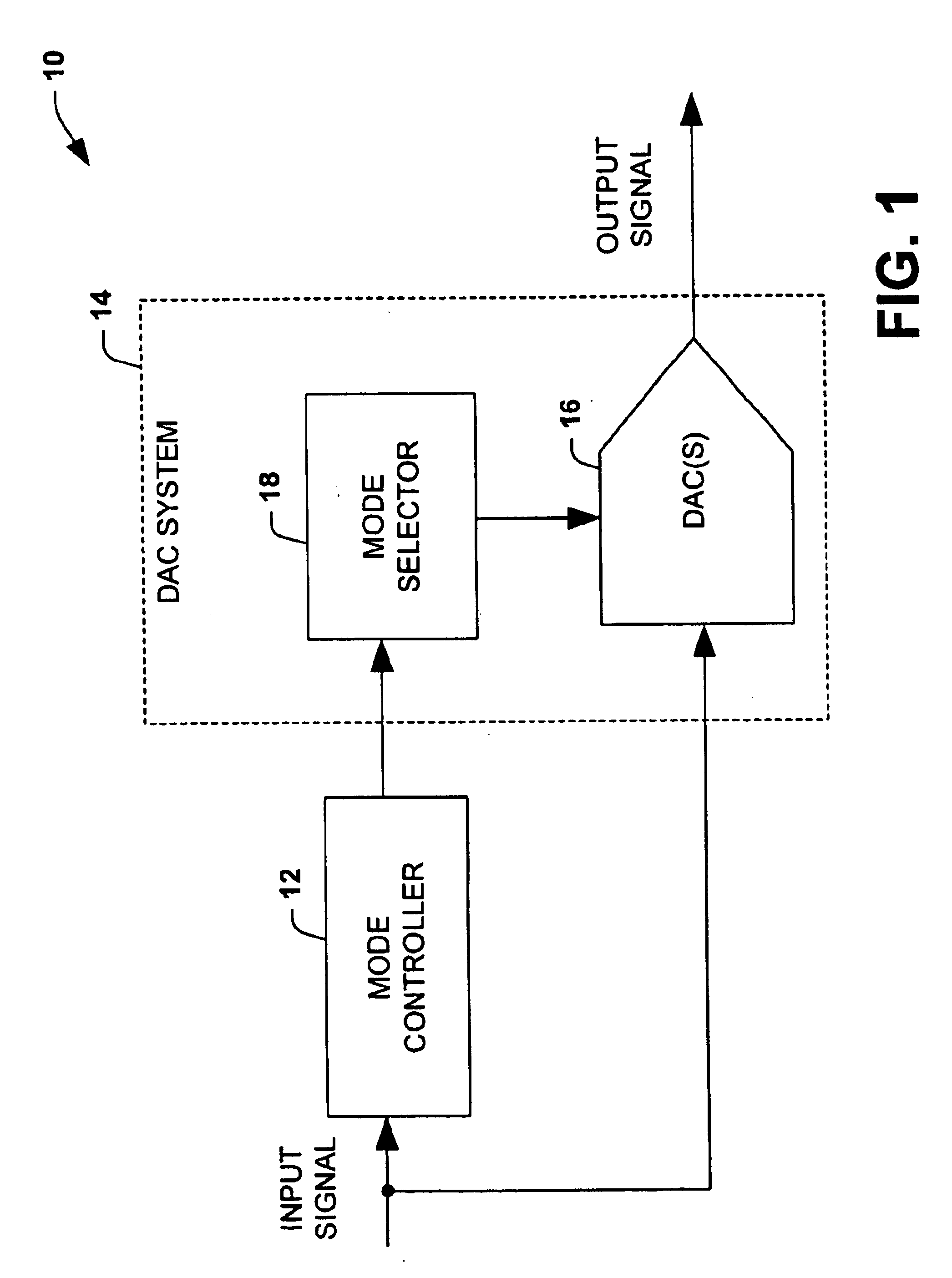
The present invention is a system for converting a digital input signal into an analog output signal with reduced quantization noise. The system includes a DAC system and a mode selector that selects the mode of operation for the DAC system based on the characteristic of the input signal. The DAC system can include one or more delta-sigma modulators, scaling devices, and extra gain switches to further reduce quantization noise. The system can also include a mode control that splits the input signal into a phase modulated component and an amplitude modulated component, and the output of the DAC device is amplified by a selected gain factor. The invention provides a way to improve the dynamic range and quality of analog signals in various applications such as communication systems.

Problems solved by technology

Transmission of multiple carriers simultaneously also results in time-varying envelopes.
This signal distortion can lead to both errors in the wanted signals and increased out-of-band emissions.
Noise sources include electronic noise, quantization noise, and spurious signals resulting from non-linearities in the DAC.
Delta-sigma DACs have very low quantization noise in selected passbands and high noise levels elsewhere.
Quantization noise that is not filtered in the signal chain is amplified and transmitted contributing to received bit-errors and causing interference in adjacent spectral regions.

Method used


Image

  • Extended range digital-to-analog conversion
  • Extended range digital-to-analog conversion
  • Extended range digital-to-analog conversion

Examples


Embodiment Construction

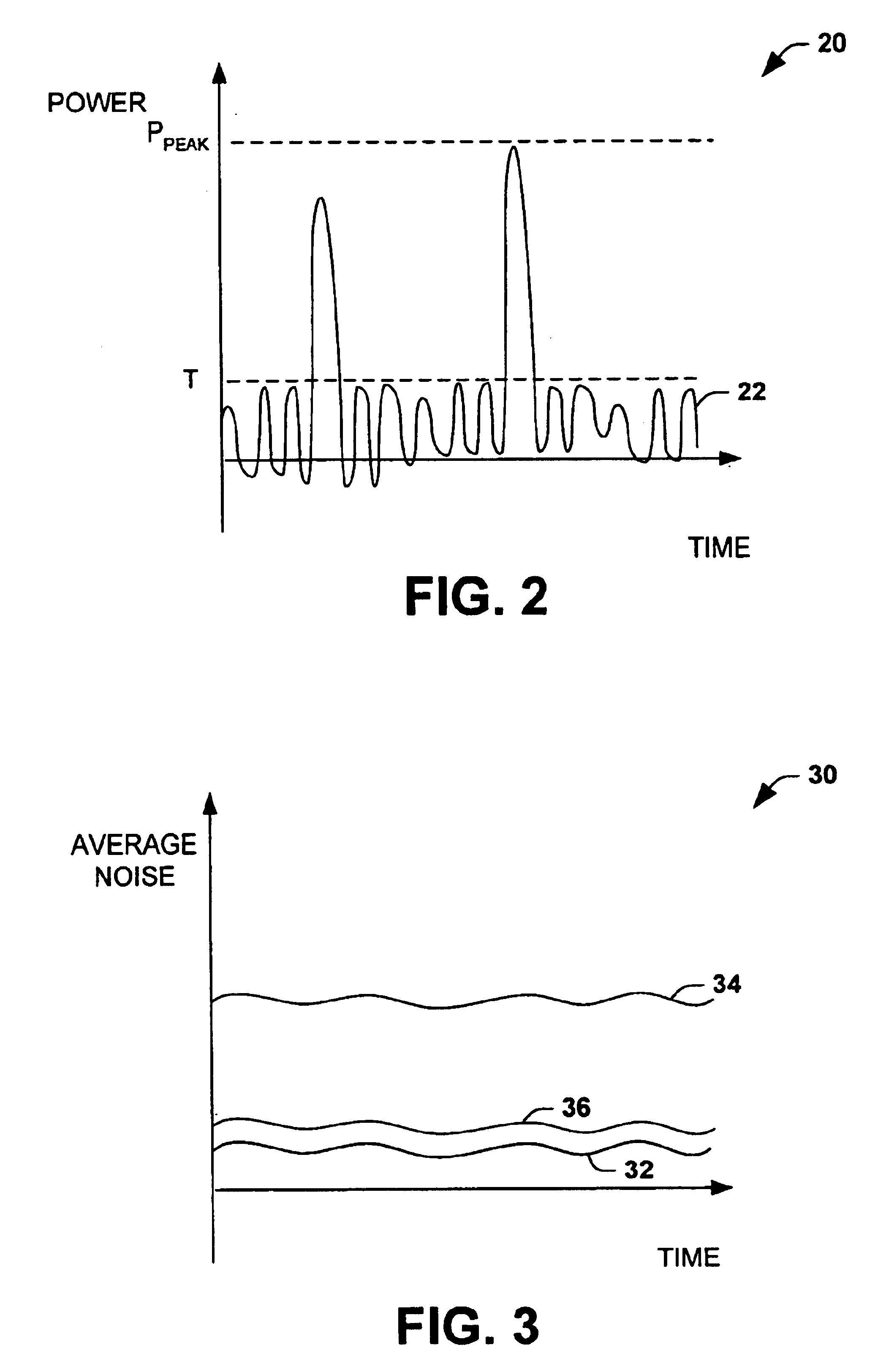
The present invention relates to a system for converting a digital signal to an analog signal. The system selects a mode of operation based upon a characteristic, such as amplitude or frequency, of the input signal. Each mode of operation corresponds to an instantaneous dynamic range and corresponding quantization noise level of a digital-to-analog converter system. The ensemble of modes provides an increased dynamic range and / or a reduced quantization noise level compared to a single mode. The input signal can thus be converted at a dynamic range matching its instantaneous characteristics. This flexible dynamic range reduces the average quantization error of the output signal. This is particularly useful in communications application, where excessive quantization error can result in out-of-band emissions and other signal distortion. Thus, the digital-to-analog conversion system of the present invention is well-suited for use within transmitters, including mobile transmitters as wel...


PUM


Abstract

A conversion system converts an input signal from a digital signal to an analog signal over an extended dynamic range. The system includes a DAC system and a mode selector. The mode selector selects a mode of operation for the digital-to-analog converter system from a plurality of modes. The mode selector selects a mode according to a characteristic of the input signal. Each of the modes is associated with an instantaneous dynamic range and quantization noise level of the DAC system. The ensemble of modes provides an improvement in total or effective dynamic range compared to any DAC component within the DAC system.

Description

The present invention relates generally to electronic devices, and more particularly to digital-to-analog conversion.Modern transmitters for applications such as cellular, personal, and satellite communications employ digital modulation techniques such as quadrature phase-shift keying (QPSK) in combination with code division multiple access (CDMA) communication. Shaping of the data pulses mitigates out-of-band emissions from occurring into adjacent spectral channels but produces time-varying envelopes. Transmission of multiple carriers simultaneously also results in time-varying envelopes. In many cases the time varying envelopes exhibit large but infrequent peaks. These peaks require digital-to-analog converters (DACs) within the transmitter to have dynamic ranges that encompass the peak values to avoid clipping the signal which would introduce significant distortion of the signal. This signal distortion can lead to both errors in the wanted signals and increased out-of-band emissi...

Claims


Application Information

Patent Timeline
Patent Type & Authority Patents(United States)
IPC IPC(8): H03M1/08H03M1/70H03M1/66H03M3/00
CPCH03M3/51H03M1/70
Inventor ROBINSON, IAN
Owner NORTHROP GRUMMAN SYST CORP
Learn More