
Water saving dual flush system of valving

a dual-flush valve and flushing technology, applied in water installations, flushing devices, construction, etc., can solve the problems of low flushing efficiency, low flushing efficiency, and large waste of water resources, so as to reduce the need for expensive recycling of treated water, the effect of simple and cost-effectiv

Inactive Publication Date: 2004-12-14
PIPENBURG CHARLES G
View PDF5 Cites 37 Cited by
  • Summary
  • Abstract
  • Description
  • Claims
  • Application Information

AI Technical Summary

Benefits of technology

"This patent describes a valving system for toilets that helps save water by converting regular toilets into water-saving toilets. The system uses a flapper valve and a second valve to control the flow of water. It can be installed in existing toilets without replacing them and can save up to 34% of water usage. The system also allows for the use of low flow toilets and can be adjusted for different flow rates and timings. Manufacturers can use this system to control the flow rate and volume of their toilets. Overall, this system provides a simple and cost-effective solution to the problem of excessive water usage in the toilet flush system."

Problems solved by technology

Drought and pollution in addition to over use of limited resources have led to fresh water shortages in many parts of the world.
Cities are now, at considerable expense, recycling waste water back in to the fresh water supply.
Some communities have limited their growth due to the lack of fresh water and over use demands on waste treatment facilities.
One of the ways in which fresh water is over used and wasted is in the toilet flush system.
These types of system require more room in the very limited water-closet space and may not be universal in their fitment.
This system requires retrofit of the existing hardware in the water closet and only allows one volume of flush for all applications.
Some of the major drawbacks of these and other current inventions are that they require major modification of existing hardware in the water-closets or they simply will not work in current water-closet toilet design systems.
Some systems are so complicated that they make reliability doubtful.
Additionally, cost and difficult instillation are barriers to popularity and wide spread use.
Some developments require the user to make due with one small inefficient volume of water for all flush needs thereby resulting in the need for multiple flushes to clear the bowl.
It has been noted by research done after low flow toilets have been installed (five year followup) that replacement low flow valves are not readily available and that most replacement valves used are not of the original low flow type and thereby the water saving effort is negated.
Follow-up research done on low flow toilets shows that approximately 42.9% of these water saving toilet systems experience problems from leaks, clogs, inefficient flush, or excessive water use.
This attempt to compromise results in over use for liquids and inefficient volumes for solids.
Low volume flushes are often the cause of clogs due to inefficient drain-line carry.
Therefore, changing to low flow single flush toilets or single flush valving will prove inefficient in many applications.
Government sponsored toilet replacement programs are expensive and problematic in that they require professional installation and create waste by scraping the old toilet.
Many people will not accept trading in their older reliable toilet for one that is of greater cost and less reliability.
Toilet replacement and water recycling programs are very long term projects that do not fulfill immediate needs to conserve water and energy resources.

Method used


Image

  • Water saving dual flush system of valving
  • Water saving dual flush system of valving
  • Water saving dual flush system of valving

Examples


embodiment

Preferred Embodiment

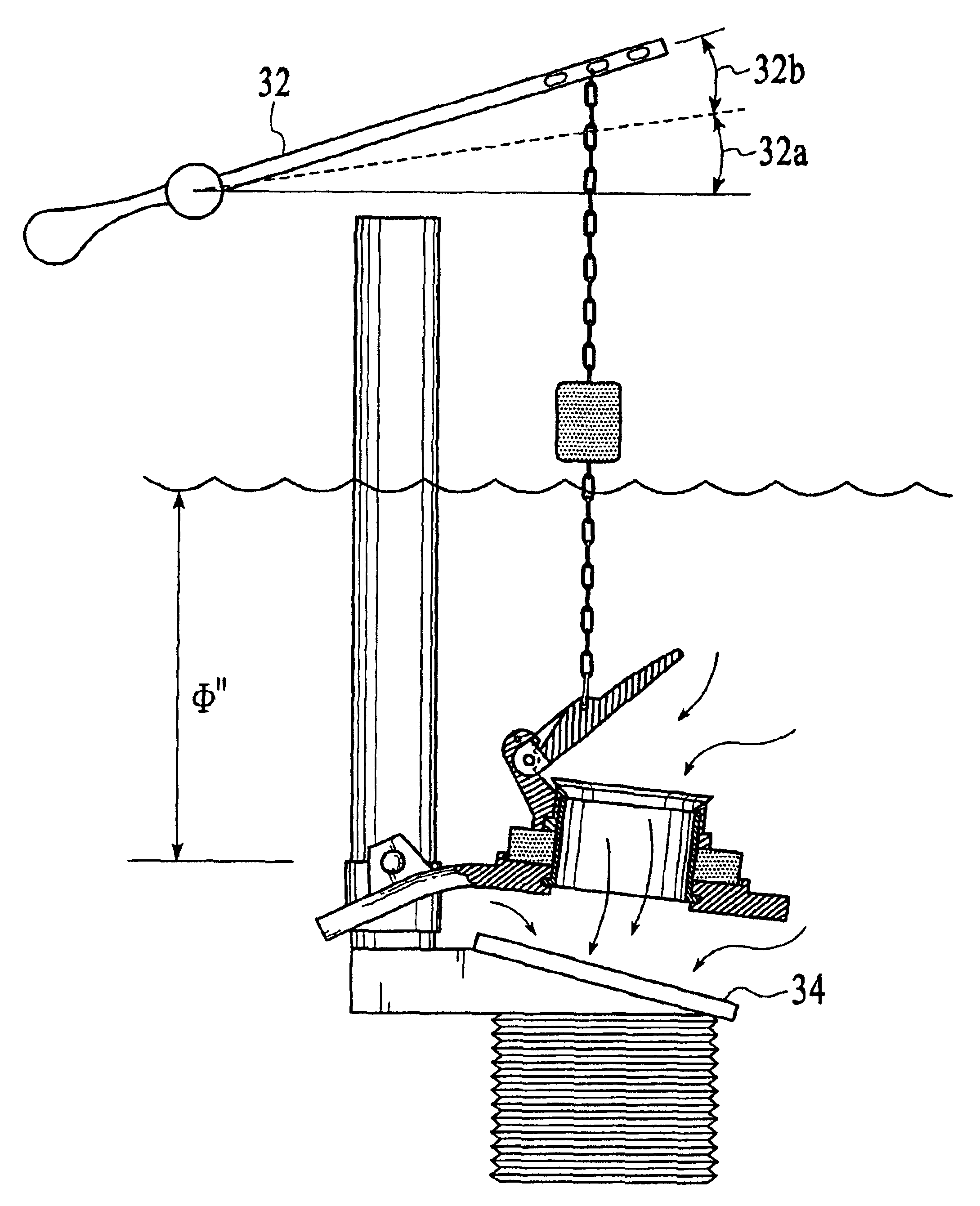
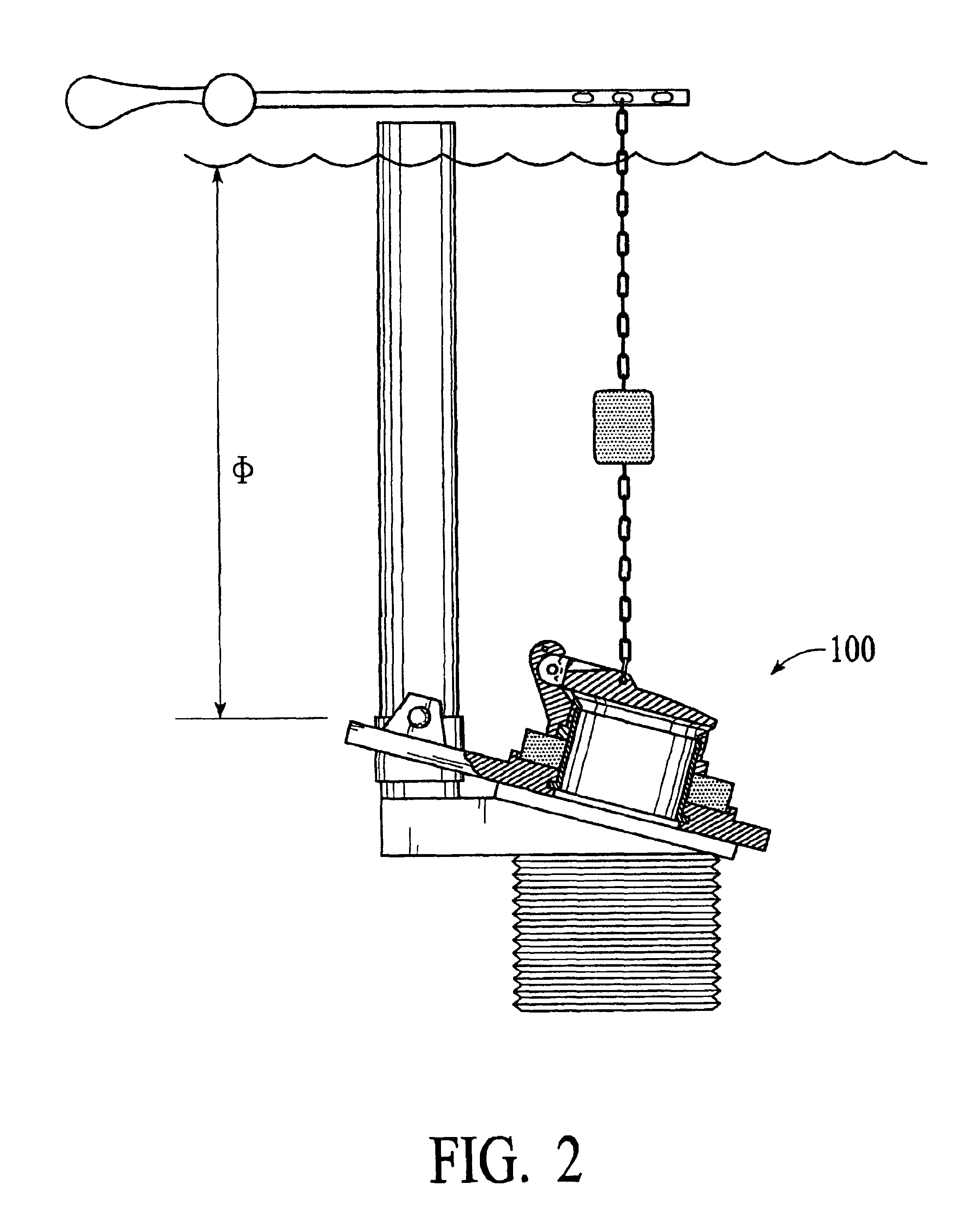
Instillation: This system of valving is designed to fit existing hardware in gravity flow type water-closets. Common flapper type valve attachment points are provided to attach to new or existing overflow pipes. A flush chain, or equivalent, is provided to attach to the new or existing flush handle arm. The instillation of this valving system converts the existing toilet, or new toilets, from flapper or ball type single flush valving to a water saving dual flush system.

Operation: Partial rotation of the flush handle will open the upper valve only and allow a preselected quantity of water to flush liquid waste. Full rotation of the flush handle will open the bottom valve and release a larger quantity of water for flushing solids. Each of the flush modes provide a positive valve release feel to the handle so that the user cannot mistakenly use the wrong flush mode. Activated flush modes will complete their flush cycle and return to the ready status automatically. A...


PUM


Abstract

A water saving dual flush system of valving assembly for toilet water-closets of the gravity flow type. This system of valving is designed to fit existing hardware in typical water-closets and convert single flush designs to dual flush water saving systems. Comprised of a flapper type bottom valve having a port located at a position above the discharge pipe of a common water-closet. The port edge of the bottom valve being molded to receive and mate to a flanged pipe end and thereby forming a watertight seal between the pipe and the bottom valve. A floatation collar being attached about the outside of the pipe. The upper end of the pipe having a upper valve seat sleeve attached. The upper valve seat sleeve being a slip-fit sleeve with a valve seat formed on the upper end and having a hinge portion incorporated on one side. The upper valve seat sleeve hinge is designed to mate to the upper valve and form together a hinged mount. The bottom end of the valve seat sleeve being flared to retain the floatation collar. The upper valve having a mating hinge mount attachment point to mate with the upper valve seat sleeve hinge. The upper valve being non-buoyant (depending on the application). The upper valve having a chain attachment point for flush actuation connection to the flush arm and thereby to the flush handle. The chain also having attached a float by which the upper valve is operatively adjusted.

Description

Not Applicable1. Field of InventionThis invention relates to plumbing products particularly to water saving dual flush valves for gravity flow toilet water-closets.2. Description of Prior ArtThe need for water conservation is widely recognized as an issue that must be addressed by all people. Drought and pollution in addition to over use of limited resources have led to fresh water shortages in many parts of the world. Some communities have placed limits on the use of water and provide for fines when users exceed their limit. Cities are now, at considerable expense, recycling waste water back in to the fresh water supply. Some communities have limited their growth due to the lack of fresh water and over use demands on waste treatment facilities.One of the ways in which fresh water is over used and wasted is in the toilet flush system. An estimated average use of 40% of the total of household water consumption is flushed from the toilet to the sewer or septic systems. It is now under...

Claims


Application Information

Patent Timeline
Patent Type & Authority Patents(United States)
IPC IPC(8): E03D1/02E03D5/09E03D5/00E03D1/14E03D1/30
CPCE03D1/142E03D5/09E03D1/306Y02A20/40
Inventor PIPENBURG, CHARLES G.
Owner PIPENBURG CHARLES G
Learn More