Motor with dynamic pressure bearing

a technology of dynamic pressure bearing and motor, which is applied in the direction of sliding contact bearing, record information storage, instruments, etc., can solve the problems of reducing the axial direction of the holder member, reducing the mechanical strength, and requiring some structural ingenuity

Inactive Publication Date: 2004-12-28
NIDEC CORP
View PDF6 Cites 40 Cited by
  • Summary
  • Abstract
  • Description
  • Claims
  • Application Information

AI Technical Summary

Benefits of technology

In one aspect of the present embodiment, the rotary hub may be provided with a fixing section that protrudes in the axial direction from an end surface in the axial direction of the rotary hub, which fixes the hub mounting section of the circular ring-shaped member through plastic deformation. The inner circumference surface of the fixing section may be formed as a regulating surface that positions the hub mounting section of the circular ring-shaped member. As a result, the hub mounting section can be readily mounted on the rotary hub with high precision due to the positioning regulating surface of the fixing section; and this results in a firmly fixed state between the hub mounting section and the rotary hub through the plastic deformation of the fixing section.
The dynamic pressure bearing motor may be further provided with a circumferential wall section that collects a coating sealer for the plastically deformed fixing section formed on the rotary hub outer side in the radial direction of the fixing section. As a result, contamination that may be caused by plastically deforming the fixing section can be favorably prevented and the lubricating fluid can be favorably prevented from flowing outside the fixing section by the coating sealer.
In the dynamic pressure bearing motor, the fluid sealing section may have a capillary sealing structure whose gap dimension gradually enlarges towards an opening of the fluid sealing section, and both of the outer circumference surface of the dynamic pressure bearing sleeve and the inner circumference surface of the main body section of the circular ring-shaped member, which together form the fluid sealing section, may have a tapered surface that slopes inward in the radial direction towards the opening of the fluid sealing section, such that the center axial line of the fluid sealing section slopes inward in the radial direction towards the opening. As a result, the centrifugal force during rotation, in addition to the inherent capillary sealing effect of the fluid sealing section, works to push inward the lubricating fluid inside the fluid sealing section, which results in an substantially favorable sealing effect.
In accordance with one embodiment of the present invention, a dynamic pressure bearing motor is equipped with a dynamic pressure bearing sleeve for supporting a rotary shaft by a dynamic pressure; a rotary hub coupled to the rotary shaft; a thrust dynamic pressure bearing section formed between the dynamic pressure bearing sleeve and the rotary hub; and a circular ring-shaped member that is placed to surround an outer circumference surface of the dynamic pressure bearing sleeve, and has a hub mounting section joined to an end surface of the rotary hub in a region radially outside of the thrust dynamic pressure bearing section and a main body section that inwardly protrudes from the hub mounting section. A fluid scaling section that prevents a lubricating fluid inside the thrust dynamic pressure bearing section from flowing outside is formed between the hub mounting section and an outer circumference surface of the dynamic pressure bearing sleeve, wherein the fluid sealing section is defined by a gap in the radial direction formed continuously from the thrust dynamic pressure bearing section. The dynamic pressure bearing sleeve includes a fallout stopper flange section that protrudes outward in the radial direction and opposes in the axial direction the main body section of the circular ring-shaped member to prevent the circular ring-shaped member from falling out in the axial direction. The inner circumference surface of the hub mounting section is positioned to oppose in the radial direction the outer circumference surface of the fallout stopper flange section of the dynamic pressure bearing sleeve.
As a result, the length of a holder member that holds a stator core can be sufficiently extended in the axial direction, and the height in the axial direction of the stator core holding section of the holder member can be extended to a position in the vicinity of the hub mounting section of the circular ring-shaped member. This results in sufficient joining force for the stator core and in a favorable control of the magnetic vibration of the stator core.
In accordance with another embodiment of the present invention, a dynamic pressure bearing motor is equipped with a rotating member that is rotatively driven in a unitary fashion with a rotary shaft; a dynamic pressure bearing member that rotatively supports the rotary shaft by dynamic pressure; and a thrust dynamic pressure bearing provided in a region where an end surface in the axial direction of the dynamic pressure bearing member and an end surface in the axial direction of the rotating member oppose each other in the axial direction. The rotating member includes a rotary hub that is made of an aluminum material and has a disk mounting section, and a thrust plate that is provided on the rotary hub and is made of an iron material and makes up a part of the thrust dynamic pressure bearing. As a result, wear on the rotary hub is controlled and the life of the dynamic pressure bearing can be extended, even when the hub and the dynamic pressure bearing member come into contact in start and stop operations.
In another aspect of the present invention, the rotary shaft can be fitted in a unitary fashion on the inner circumference side of the thrust plate and the rotating member can be mounted in a unitary fashion on the outer circumference side of the thrust plate. With such a structure, the bonding strength between the hub made of an aluminum material and the rotary shaft can be increased.

Problems solved by technology

However, an aluminum alloy hub that fits to an aluminum alloy disk is relatively soft and the mechanical strength obtained when the hub is joined with a rotary shaft is not sufficient; this consequently requires some structural ingenuity.
As described above, when forming a thrust bearing section by utilizing a top end surface of a dynamic pressure bearing sleeve, a circular ring-shaped member that serves as a fallout stopper member is positioned to project out to the position of a holder member that holds a stator core; this inevitably causes the holder member to be shortened by that much in the axial direction.
This results in a shorter joining length between the holder member and the stator core, which causes the holding strength of the stator core to be reduced, which in turn leads to larger electromagnetic vibration of the stator core.
Furthermore, since the joining length in the axial direction of the circular ring-shaped member would also be insufficient, the joining strength of the circular ring-shaped member would lend to be insufficient; and dust from adhesive in a joining section of the circular ring-shaped member could enter a sealing section positioned in the vicinity of the circular ring-shaped member and cause contamination.
However, by doing so, a circular ring-shaped member that serves as a fallout stopper member for a rotary hub cannot be mounted because of the holder member, and this leaves no choice but to provide the fallout stopper member parallel in the axial direction to a radial bearing section.
However, using aluminum alloy as the material for the rotary hub that makes up a thrust bearing does not provide sufficient hardness; consequently, the rotary hub that makes up the thrust bearing comes into contact with an end surface of a sleeve, which serves as a dynamic pressure bearing member, whenever there is a start or stop operation, which causes the rotary hub to wear quickly and the dynamic pressure bearing to have a short life.

Method used


Image

  • Motor with dynamic pressure bearing
  • Motor with dynamic pressure bearing
  • Motor with dynamic pressure bearing

Examples


Embodiment Construction

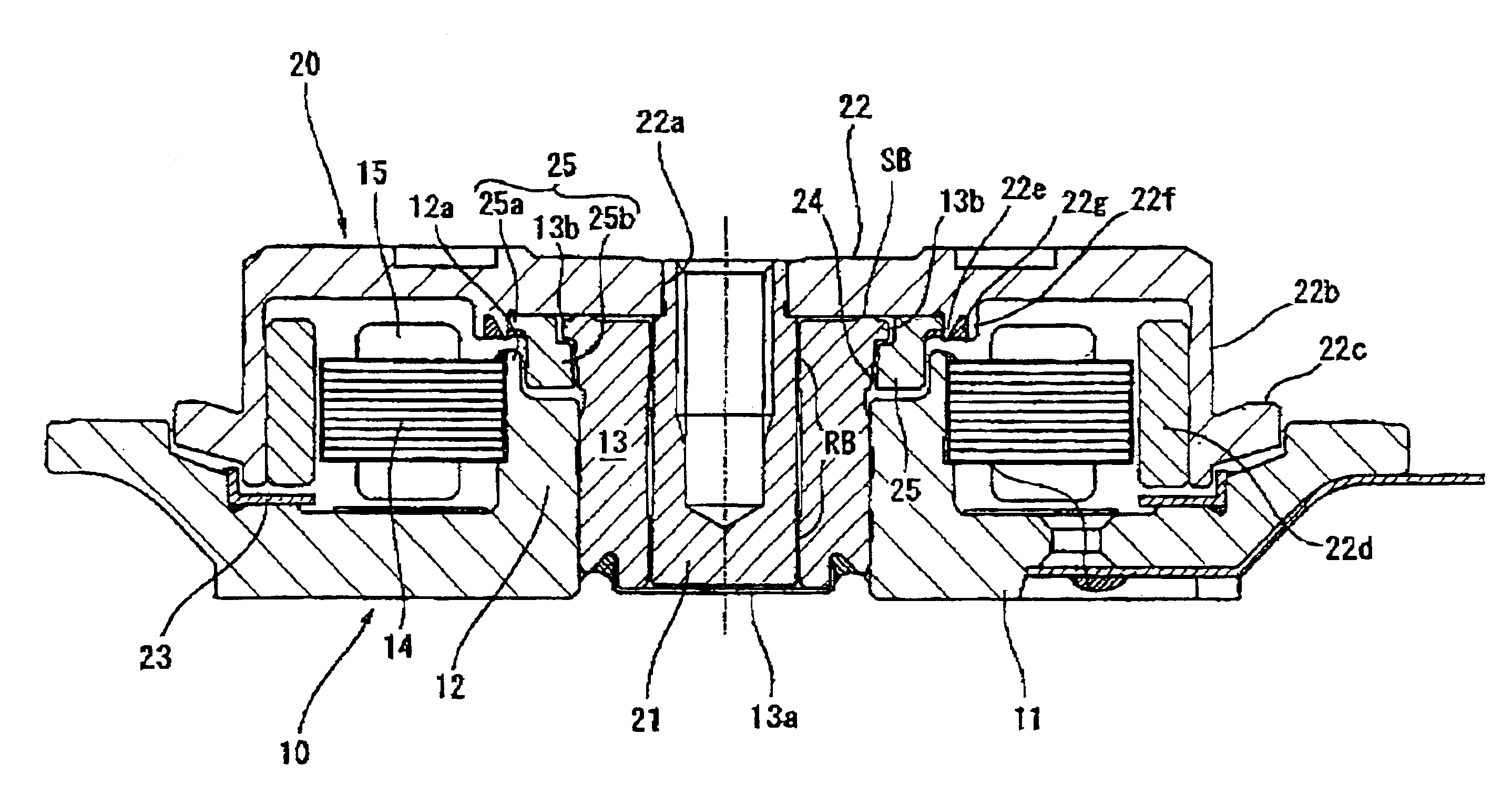
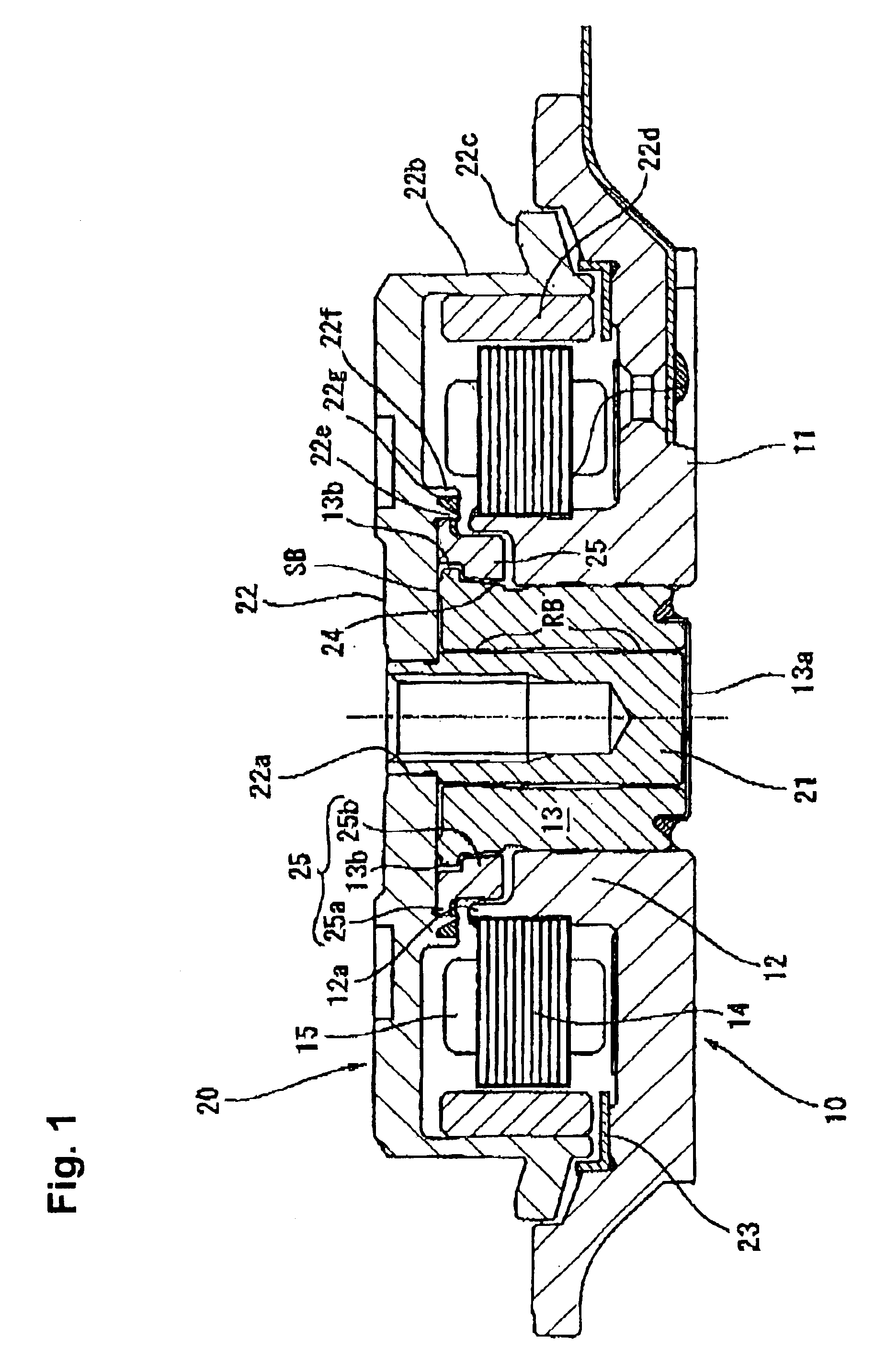
Embodiments of the present invention are described in detail below with reference to the accompanying drawings. First, an overview of a hard disk drive device (HDD) as one example employing a dynamic pressure bearing motor in accordance with an embodiment of the present invention is described.

The entire shaft rotation-type HDD motor shown in FIG. 1 is formed from a stator assembly 10, which is a fixed member, and a rotor assembly 20, which is a rotating member assembled onto the top of the stator assembly 10. The stator assembly 10 has a fixed frame 11 screwed to a fixed base, not shown. The fixed frame 11 is formed with an aluminum material to achieve a lighter weight, and includes a ring-shaped bearing holder 12 formed upright in the generally center part thereof. On an inner circumference surface of the ring-shaped bearing holder 12 is provided a dynamic pressure bearing sleeve 13, which is a fixed bearing member formed in the shape of a hollow cylinder and joined to the bearing ...


PUM

PropertyMeasurementUnit
dynamic pressureaaaaaaaaaa
circumferenceaaaaaaaaaa
heightaaaaaaaaaa

Abstract

A dynamic pressure bearing motor includes a rotary shaft, a rotary hub coupled to the rotary shaft, a dynamic pressure bearing sleeve that supports the rotary shaft by dynamic pressure and has a fallout stopper flange section that protrudes outward in the radial direction, a thrust dynamic pressure bearing section formed in an axial direction between the dynamic pressure bearing sleeve and the rotary hub, and a circular ring-shaped member that surrounds an outer circumference surface of the dynamic pressure bearing sleeve. The circular ring-shaped member has a hub mounting section that connects to an end surface of the rotary hub in a region radially outside the thrust dynamic pressure bearing section, and a main body section that protrudes inward from the hub mounting section. An inner circumference surface of the hub mounting section of the circular ring-shaped member opposes in the radial direction an outer circumference surface of the fallout stopper flange section of the dynamic pressure bearing sleeve, and the main body section of the circular ring-shaped member opposes in the axial direction the fallout stopper flange section of the dynamic pressure bearing sleeve to prevent the dynamic pressure bearing sleeve from falling out in the axial direction.

Description

1. Field of the InventionThe present invention relates to a motor with dynamic pressure bearing that is equipped with a dynamic pressure bearing member that supports a rotary shaft by utilizing dynamic pressure generated in a lubricating fluid.2. Related Background ArtIn recent years, development of dynamic pressure bearing motors, in which a dynamic pressure bearing member or dynamic pressure bearing sleeve supports a rotary shaft by utilizing dynamic pressure generated in lubricating fluid, has been in progress for bearing apparatuses that allow rotating bodies to rotate at high-speed and with high precision to be used in various rotatively driven apparatuses. An effort is underway to make the entire apparatus thinner for such dynamic pressure bearing motors, and forming a thrust bearing section by utilizing an end surface in the axial direction of a dynamic pressure bearing sleeve has been proposed in order to achieve such thinner apparatus.In such dynamic pressure bearing motors...

Claims


Application Information

Patent Timeline
Patent Type & Authority Patents(United States)
IPC IPC(8): F16C33/04F16C33/10F16C17/26F16C17/04F16C17/02F16C17/00G11B19/20
CPCF16C17/107G11B19/2018F16C33/107F16C2370/12
Inventor GOMYO, MASATOSUGINOBU, SHINGO
Owner NIDEC CORP
Why Eureka
Try Eureka