Method and system for restraining road vehicle on a transport vehicle

a technology for transport vehicles and road vehicles, applied in the direction of vehicle carriers, load securing, item transportation vehicles, etc., can solve the problems of transported road vehicles being subjected to an impact force either in front or in the rear direction, and achieve the effect of soft dissipation of kinetic energy

Inactive Publication Date: 2004-12-28
4294661 CANADA
View PDF12 Cites 45 Cited by
  • Summary
  • Abstract
  • Description
  • Claims
  • Application Information

AI Technical Summary

Benefits of technology

A further feature of the present invention is to provide a catcher tire abutment device as above-mentioned and which is lightweight, economical to produce and easy to install and remove from a flooring surface without the use of tools.
According to a still further broad aspect of the present invention when the tires of one of the front or rear pairs of wheels contact the arresting surface of the primary wheel restraining devices, the tires compress against the arresting surface whereby to absorb impact by deformation of the tires and wherein the arresting surface simultaneously cause the tires to move upward whereupon the weight of the road vehicle provides a downward restoring load to assist the road vehicle to return to the transport location when the arresting surface of the catcher tire abutment devices are contacted by the tires of the other pair of wheels. Accordingly, the shock is absorbed sequentially by delayed contact which includes time lapse provided by the road vehicle displacement, the tire deformation and the downward load buildup during upward movement of the tires on the arresting surface of the primary wheel restraining devices all of which provides for a soft dissipation of the kinetic energy of the road vehicle being displaced by an impact force.
According to a still further broad aspect of the present invention there is provided a system for restraining a road vehicle on a vehicle support surface of a transport vehicle. The system comprises providing, for each road vehicle, four primary wheel restraining devices having an arresting surface and securing means for attaching same to the vehicle support surface with the arresting surface positioned adjacent a thread face of a tire of front and rear pairs of wheels of the vehicle and on an outward side of the pairs of wheels thereby establishing a transport location of the road vehicle on the vehicle support surface between the four primary wheel restraining devices. The system also provides four catcher tire abutment devices also having an arresting surface and securing means for attaching same to the vehicle support surface an approximate predetermined distance adjacent the thread face on an inward side of each tire of the pairs of wheels. The approximate predetermined distance is calculated whereby the arresting surface of the catcher tire abutment device is contacted by the thread face of a pair of the wheels a predetermined time after a vehicle at the transport location has been subjected to an impact force to permit the arresting surface of the primary wheel restraining devices to be contacted first by the tires of the wheels of one of the front and rear pairs of wheels whereupon the tires compress against the arresting surface, to absorb impact by deformation of the tires, while causing the wheels of the vehicle to move upward whereby the weight of the road vehicle provides a downward restraining load to assist the road vehicle to return to the transport location when the arresting surface of the catcher tire abutment devices are contacted by the tires of the other pair of wheels.

Problems solved by technology

However, if the transport vehicle, such as a railway flatbed vehicle is subjected to an abrupt stop or starts abruptly or is impacted by other flatbed during interconnection, the transported road vehicles are subjected to an impact force from either a front or a rear direction.

Method used


Image

  • Method and system for restraining road vehicle on a transport vehicle
  • Method and system for restraining road vehicle on a transport vehicle
  • Method and system for restraining road vehicle on a transport vehicle

Examples


Embodiment Construction

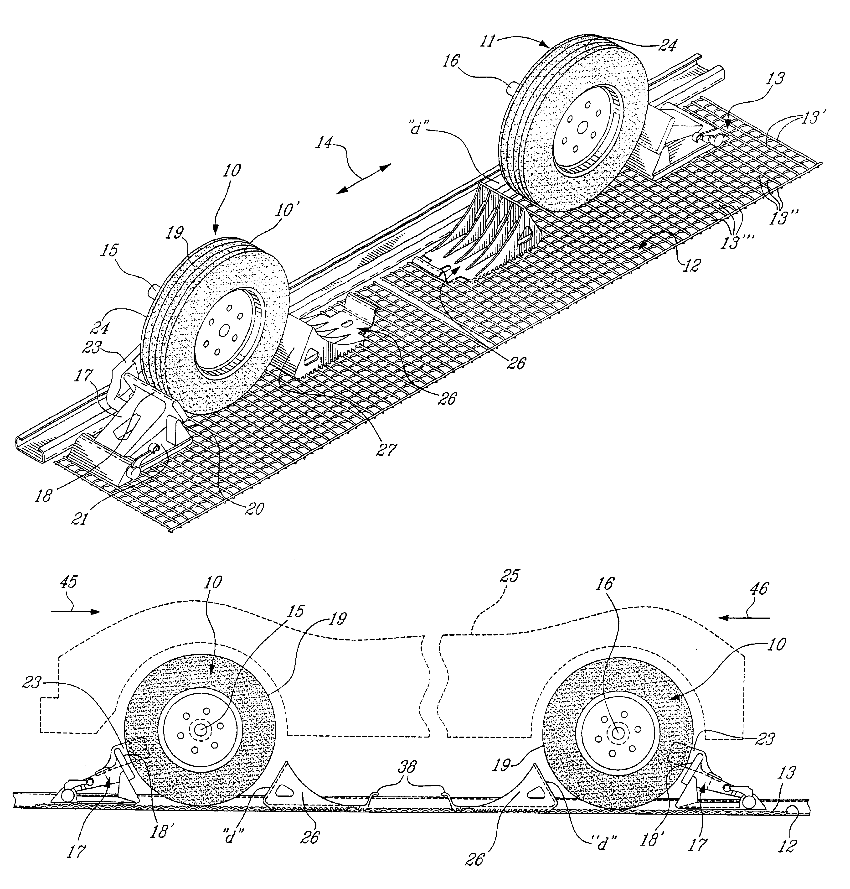
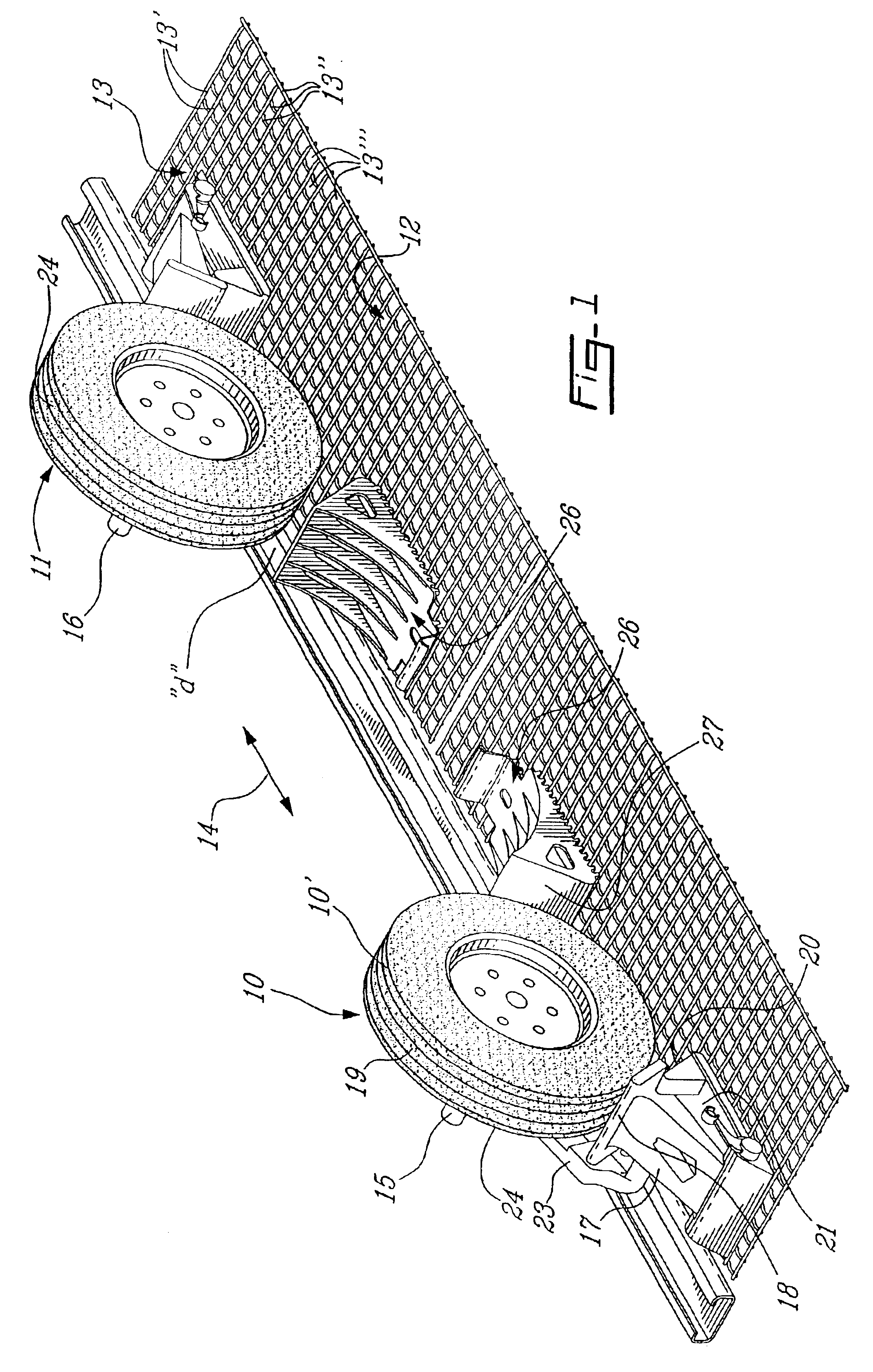
Referring now to the drawings and more particularly to FIG. 1 there is shown the front wheel 10 and rear wheel 11 of a front and rear pair or wheels of a road vehicle being transported on a support surface 12 of a transport vehicle. The support surface 12 is hereinshown as a grating 13 formed of transversely welded steel rods, herein transverse rods 13' extending transverse to the longitudinal axis 14 of the road vehicle and axial rods 13" extending in the direction of the longitudinal axis 14. Although only one of the front wheels 10 and rear wheels 11 are hereinshown it is to be understood that there are two of these wheels 10 connected to a front axle 15 and two wheels 11 connected to the rear axle 16 but for simplicity of illustration of the system as herein described only one wheel of the front pair of wheels 10 and one of the rear pair of wheels 11 is shown. It is also pointed out that the transport vehicle could be a railway vehicle or a tractor trailer type highway vehicle o...


PUM


Abstract

A method and a system including a catcher tire abutment device is described for restraining road vehicles transported on a support surface of a transport vehicle. Primary wheel restraining devices are secured to the support surface on outward sides of pairs of wheels of each road vehicle adjacent the thread surface of the wheels. A catcher tire abutment device is also secured to the support surface an approximate predetermined distance spaced adjacent the thread face on inward sides of front and rear pairs of wheels of the vehicle. When the road vehicles are subjected to an impact force, from either a front or rear direction, kinetic energy from the impacted vehicle is absorbed and dissipated softly in a sequential manner by (a) contact of the tires of one of the front and rear pairs of wheels against an arresting surface of the primary wheel restraining devices and (b) by the tires of the other pair of wheels contacting the arresting surface of the catcher tire abutment devices.

Description

The present invention relates to a method and a system as well as a catcher tire abutment device for restraining a road vehicle on a vehicle support surface of a transport vehicle and maintaining the transported road vehicle in a transport location when subjected to an impact force from either a front or rear direction.References made to my earlier U.S. Pat. Nos. 5,302,063 and 5,312,213 which relate to a wheel chuck which is securable to a grating, of a transport vehicle to prevent axial displacement and lateral shifting motion of a road vehicle being transported. With these wheel chucks it is pointed out that it is not necessary to strap any wheel or tie down the vehicle by the use of chains connected to steel runners in the support surface, such as the floor of a railway flatbed vehicle. With many prior art devices, tools are required in order to secure these chains or straps to restrain the transported vehicle The wheel chucking system as described in my above referenced patents ...

Claims


Application Information

Patent Timeline
Patent Type & Authority Patents(United States)
IPC IPC(8): B60P3/077B60P3/06
CPCB60P3/077
Inventor WINSOR, ROBERT
Owner 4294661 CANADA
Why Eureka
Try Eureka