Fuel injector with feedback control

a fuel injector and feedback technology, applied in the direction of fuel injecting pumps, machines/engines, instruments, etc., can solve the problems of increased control volume pressure and closing of needle valves, nozzle valve opening and closing characteristics are sensitive, and design does not offer feedback information on actual valve lift. , to achieve the effect of minimizing fuel consumption

Inactive Publication Date: 2005-01-04
CUMMINS INC
View PDF39 Cites 58 Cited by
  • Summary
  • Abstract
  • Description
  • Claims
  • Application Information

AI Technical Summary

Benefits of technology

It is, therefore, one object of the present invention to overcome the deficiencies of the prior art and to provide a fuel injector nozzle assembly which better enables the engine to meet future diesel engine exhaust emission requirements while minimizing fuel consumption.
A still further object of the present invention is to provide a fuel injector which is capable of accurately and variably controlling the timing of nozzle valve opening and closing, the length of the injection event and the rate at which the nozzle valve opens to provide optimum control over fuel injection metering and rate shaping.

Problems solved by technology

Opening of the injection control valve causes a reduction in the fuel pressure in the control volume resulting in a pressure differential which forces the needle valve open, and closing of the injection control valve causes an increase in the control volume pressure and closing of the needle valve.
Although these systems provide some control over fuel metering, nozzle valve opening and closing characteristics are sensitive to injection pressure, component tolerances and wear, fuel properties and temperature.
However, this design does not offer any feedback information on actual valve lift which can be used for metering control.
In addition, the control valve element engages a valve seat formed on the movable needle valve element and therefore may provide insufficient sealing in all situations as compared to a stationary valve seat.

Method used


Image

  • Fuel injector with feedback control
  • Fuel injector with feedback control
  • Fuel injector with feedback control

Examples


Embodiment Construction

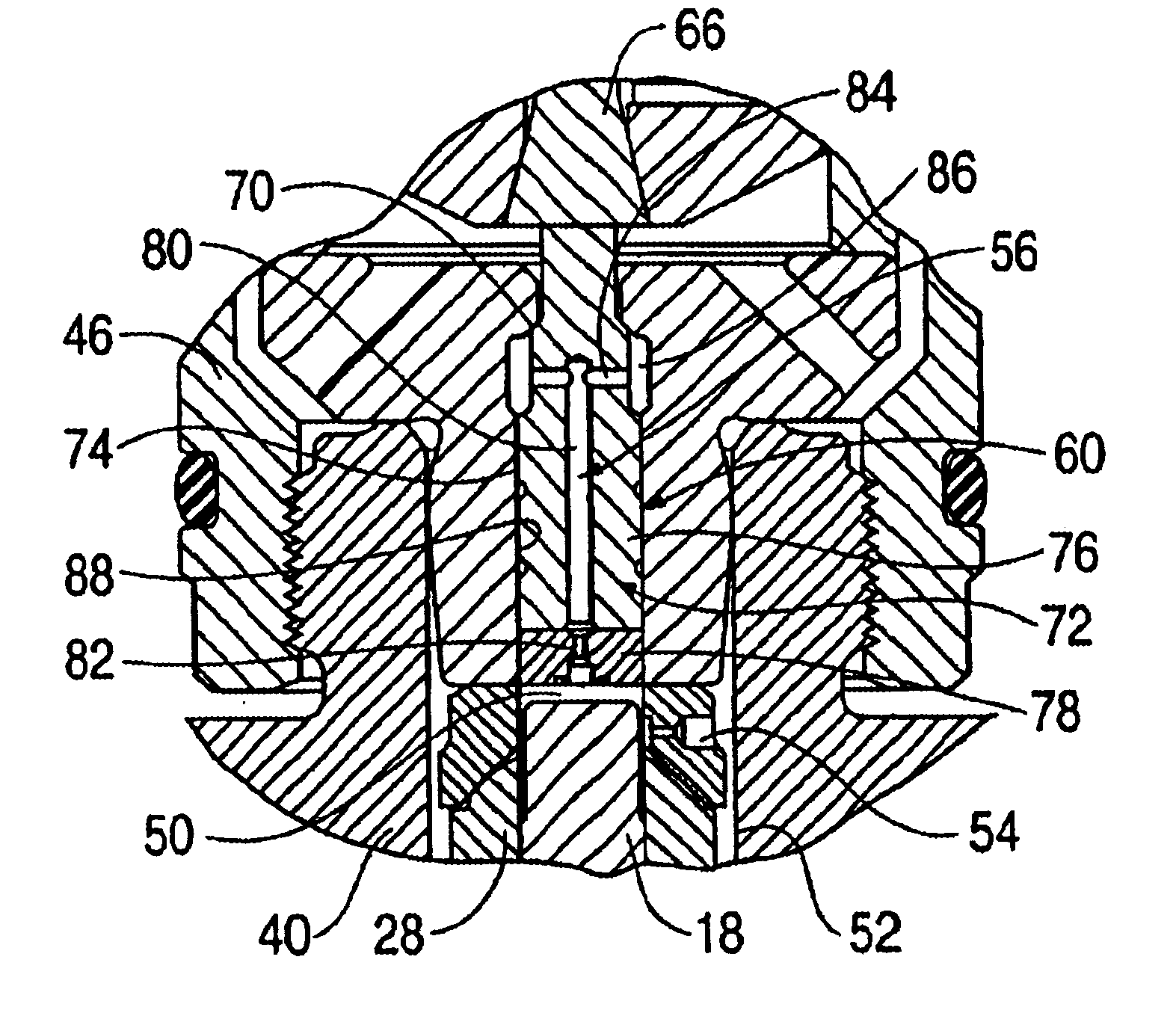
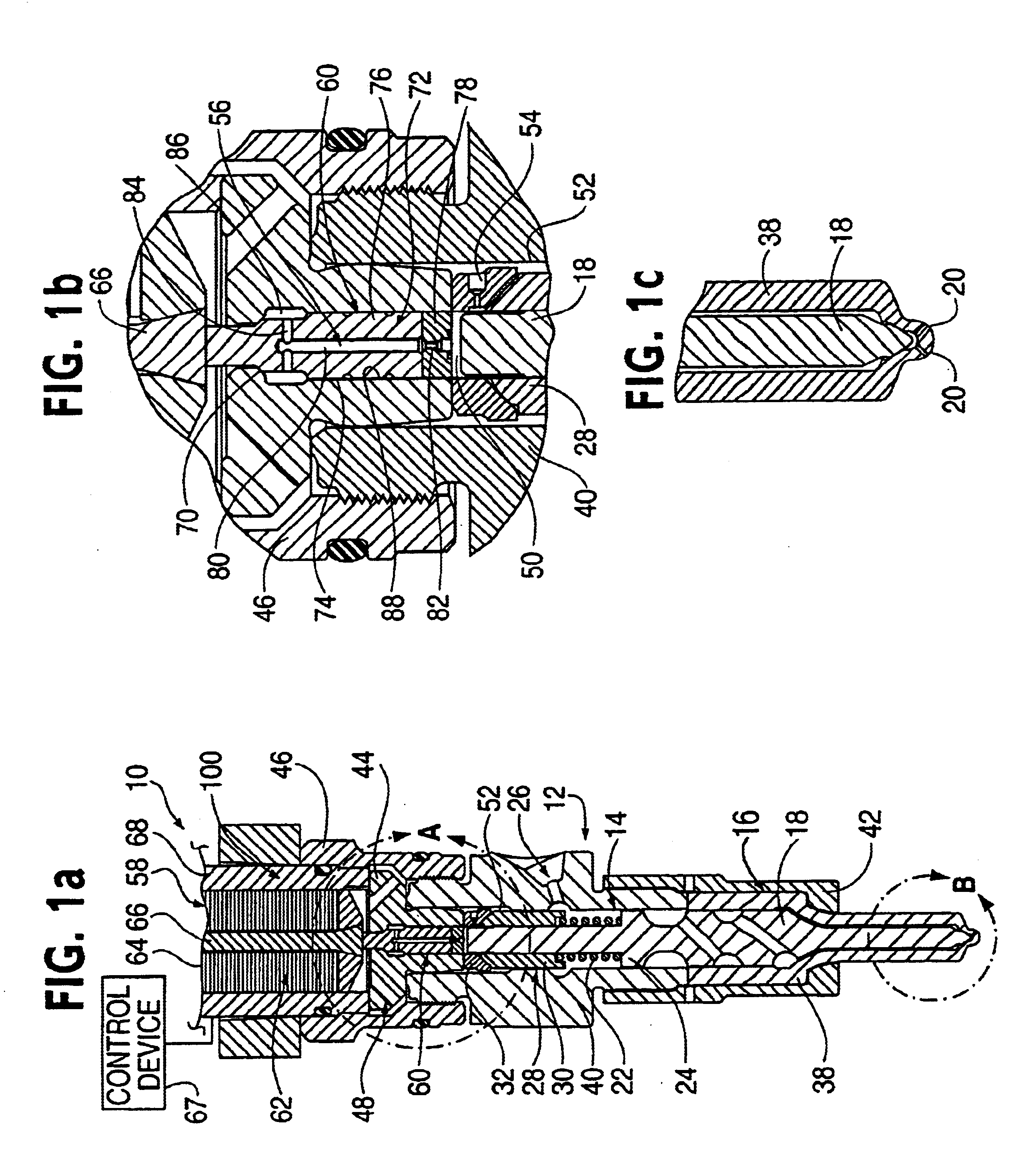
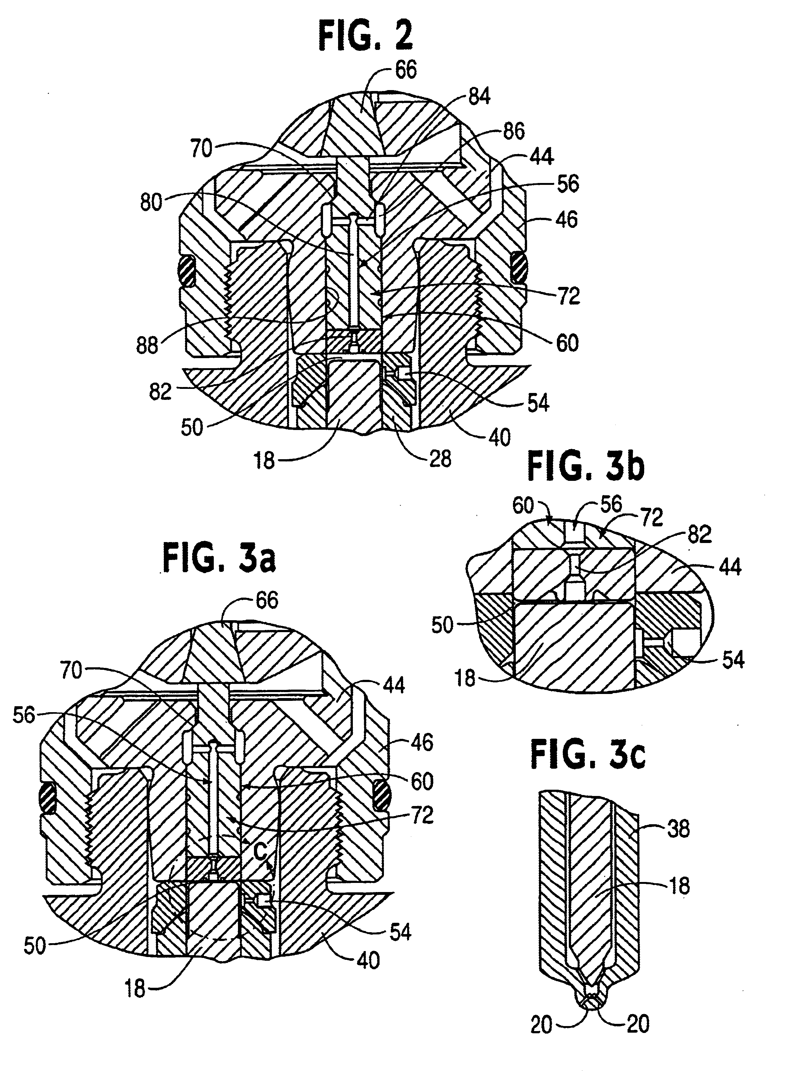
Referring to FIG. 1a, there is shown a closed nozzle fuel injector of the present invention, indicated generally at 10, which functions to effectively permit accurate and variable control of fuel metering by, in part, providing an improved feedback signal for accurate control of fuel metering and delivery. Fuel injector 10 is comprised of an injector body 12 having a generally elongated, cylindrical shape which forms an injector cavity 14. The lower portion of fuel injector body 12 includes a closed nozzle assembly, indicated generally at 16, which includes a nozzle valve element 18 reciprocally mounted for opening and closing injector orifices 20 formed in body 12 thereby controlling the flow of injection fuel into an engine combustion chamber (not shown).

Nozzle valve element 18 is preferably formed from a single integral piece structure and positioned in one end of injector cavity 14. A bias spring 22 is positioned in injector cavity 14 for abutment against a land 24 formed on noz...


PUM


Abstract

An injector is provided which includes a nozzle valve element, a control volume, and an injection control valve including a control valve member for controlling fuel flow from the control volume so as to control nozzle valve movement. Importantly, the injector includes a nozzle valve lift detecting device for detecting nozzle valve lift and providing a nozzle valve element lift feedback signal. Feedback signals are improved and control valve member oscillations are minimized by positioning a valve seat associated with the control valve member a spaced distance from the control volume, positioning a drain orifice such that the nozzle valve element restricts flow through a drain circuit when in an open position and extending the control valve member from the valve seat to the control volume to form an end wall of the control volume.

Description

TECHNICAL FIELDThe invention relates to an improved fuel injector which effectively controls fuel metering by providing a feedback signal indicative of valve movement.BACKGROUND OF THE INVENTIONIn most fuel supply systems applicable to internal combustion engines, fuel injectors are used to direct fuel pulses into the engine combustion chamber. A commonly used injector is a closed-nozzle injector which includes a nozzle assembly having a spring-biased nozzle valve element positioned adjacent the nozzle orifice for resisting blow back of exhaust gas into the pumping or metering chamber of the injector while allowing fuel to be injected into the cylinder. The nozzle valve element also functions to provide a deliberate, abrupt end to fuel injection thereby preventing a secondary injection which causes unburned hydrocarbons in the exhaust. The nozzle valve is positioned in a nozzle cavity and biased by a nozzle spring to block fuel flow through the nozzle orifices. In many fuel systems,...

Claims


Application Information

Patent Timeline
Patent Type & Authority Patents(United States)
IPC IPC(8): F02M65/00F02M59/00F02M59/46F02M47/02F02M63/00F02M51/06
CPCF02M47/027F02M63/0026F02M63/0043F02M65/005F02M63/004F02M2200/28
Inventor CROFTS, JOHN D.TRUMAN, III, ARTHUR C.SUNG, JUNG-MIN C.RAUZNITZ, PETER
Owner CUMMINS INC
Why Eureka
Try Eureka