Processing tank with improved quick dump valve

a technology of quick dump valve and processing tank, which is applied in the direction of valve housing, cleaning using liquids, mechanical equipment, etc., can solve the problems that the transducer cannot withstand such severe movement and the whole assembly undergoes significant mechanical shock, and achieves less mechanical shock

Inactive Publication Date: 2005-01-04
IMTEC ACCULINE
View PDF17 Cites 3 Cited by
  • Summary
  • Abstract
  • Description
  • Claims
  • Application Information

AI Technical Summary

Benefits of technology

The structure of the present invention improves upon the prior art in at least two aspects. One, the fixed bottom wall assembly experiences far less mechanical shock than prior art moving bottom wall designs. Thus the transducer is expected to have a far longer MTBF. Secondly, before dumping, the liquid in the tank is statically resting against the tank bottom; when th...

Problems solved by technology

First, the transducer cannot withstand such severe movement, the transducer typically being formed of a plurality of brittle crystalline members secured with adhesives to a rigid transmitting material such as, but not limited to, alumin...

Method used


Image

  • Processing tank with improved quick dump valve
  • Processing tank with improved quick dump valve
  • Processing tank with improved quick dump valve

Examples


Embodiment Construction

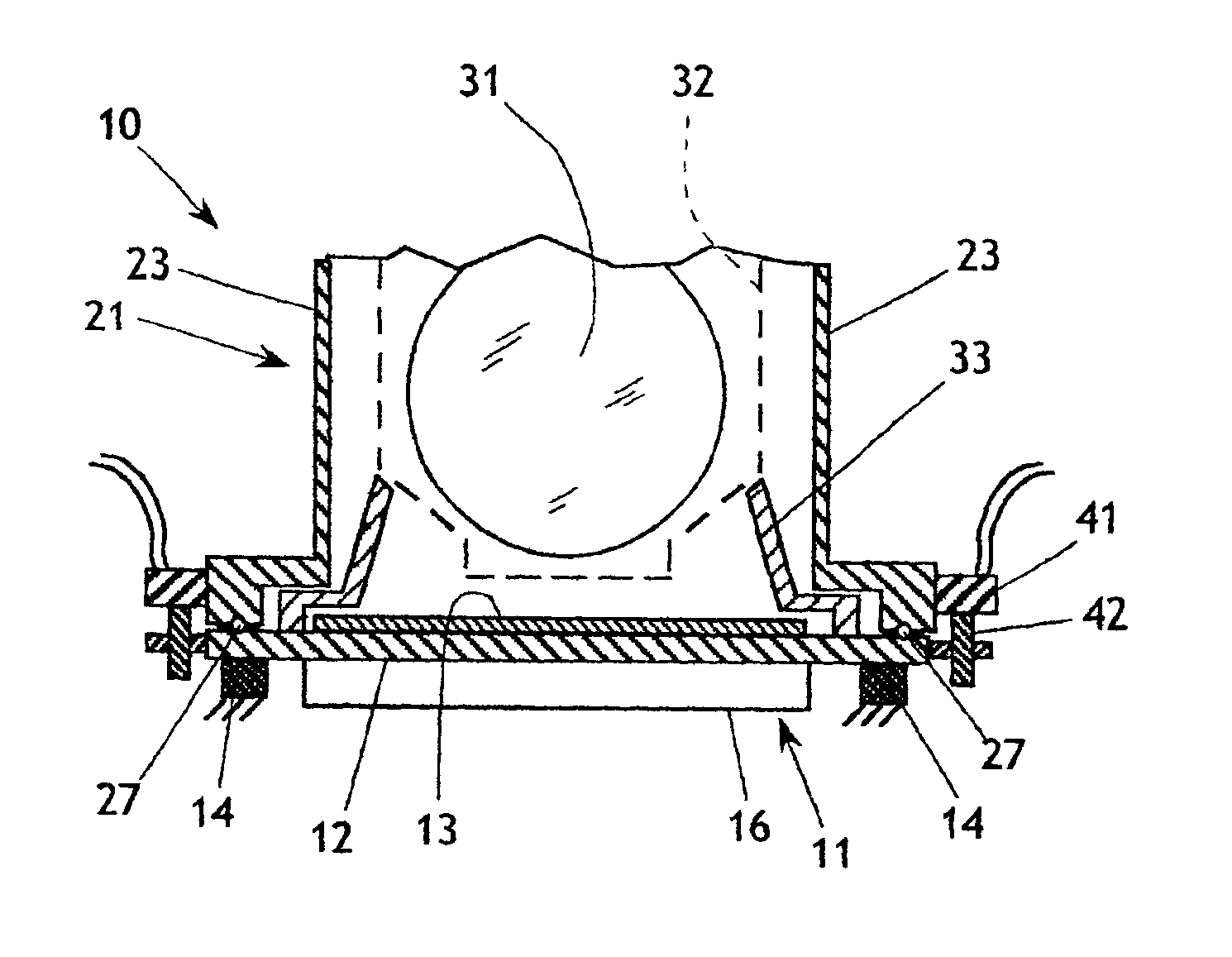
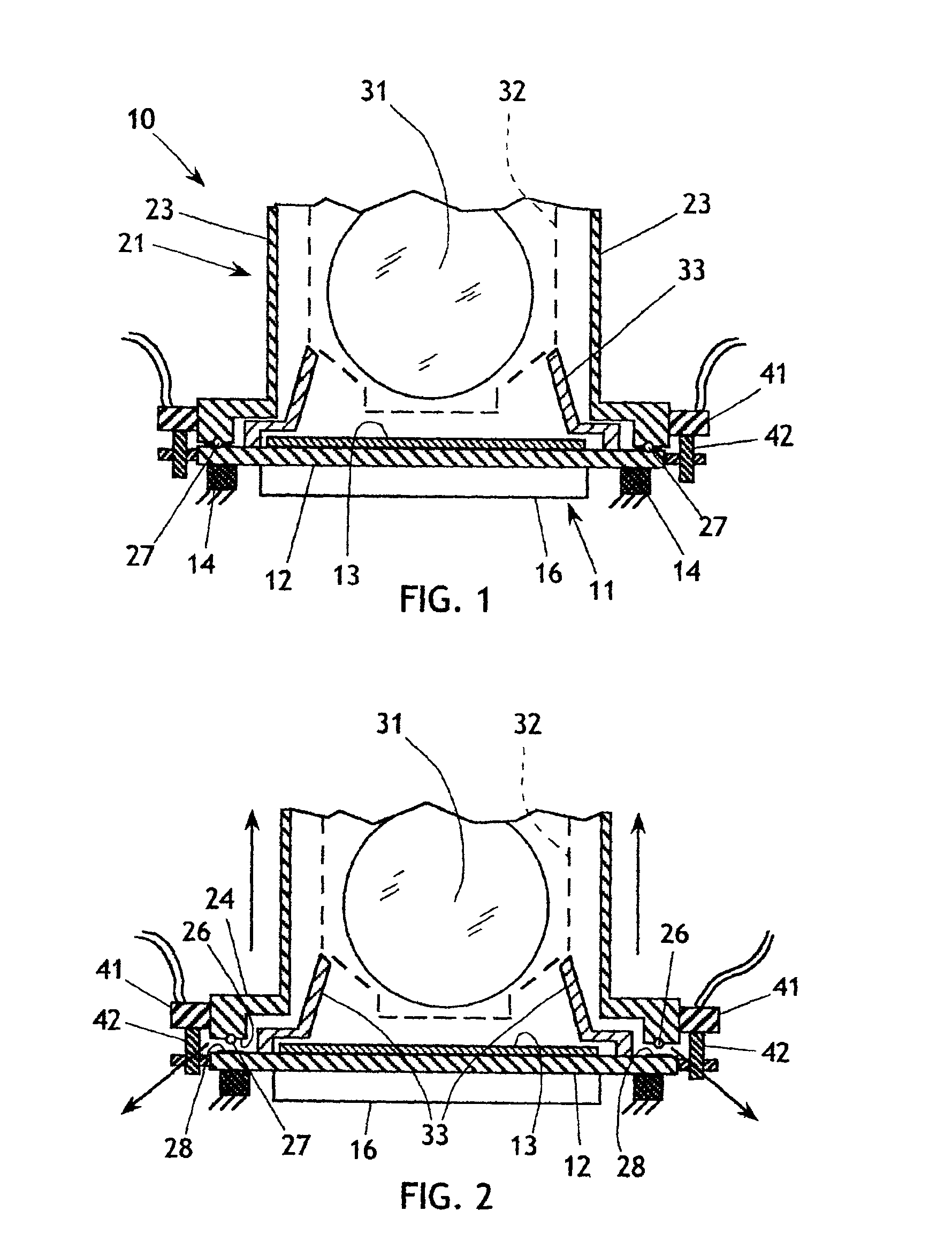
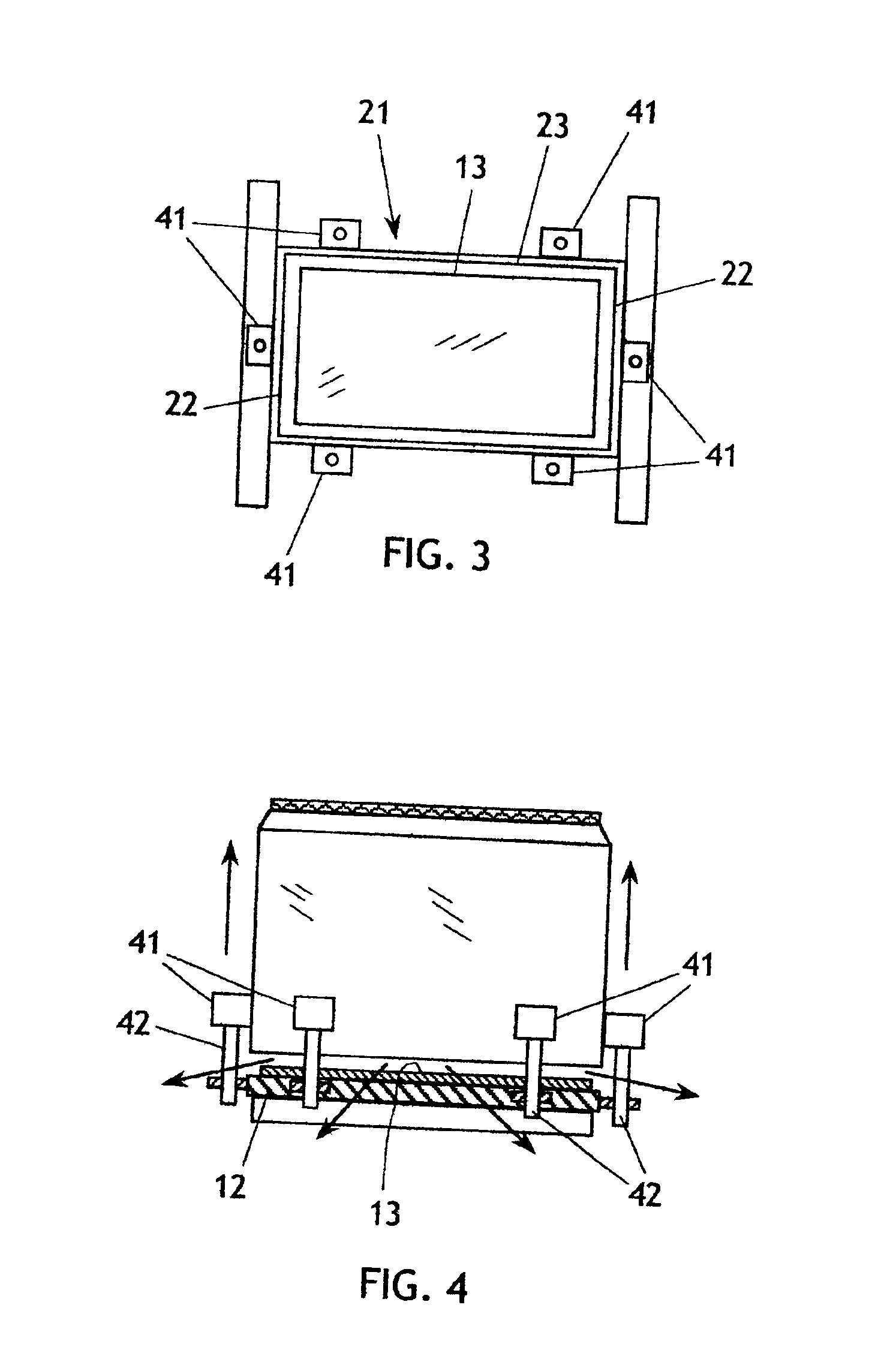
The present invention generally comprises a cleaning tank for substrates, such as semiconductor wafers, that provides a unique and beneficial quick dump (quick discharge) valve design. With regard to FIGS. 1-5, in one embodiment of the invention the tank 10 of the invention includes a bottom wall assembly 11, comprised of a bottom panel 12 and an acoustic transducer 13 secured to the upper surface of the panel 12. The bottom panel 12 is secured to a fixed support 14, so that the bottom wall assembly is immobilized and cannot move. A housing 16 depends from the panel 12 and encloses the electronics that operate the transducer 13.

The tank 10 also includes a side wall assembly 21, comprised of paired end walls 22 and paired side walls 23 arranged in a generally rectangular format and joined to form a contiguous side wall. A flange 24 extends outwardly from the lower edge of the contiguous side wall. The flange 24 extends continuously and includes a lower surface 26 that supports a seal...


PUM


Abstract

A liquid process tank that provides a quick dump feature includes a fixed bottom wall assembly and moveable tank side walls that contain liquid and also act as a quick dump valve for the liquid. The bottom wall assembly includes an acoustic transducer secured thereto. The tank side walls are secured to a plurality of linear actuators adapted for vertical movement. A seal is secured to the lower edge of the side wall assembly to impinge on a land surface that extends about the perimeter of the bottom wall assembly. The linear actuators are retracted to draw join the bottom and side wall assemblies to retain liquid, or activated in unison to drive the tank walls upwardly from the fixed bottom wall assembly, creating a bottom opening in the tank that quickly discharges all the liquid from the tank.

Description

BACKGROUND OF THE INVENTIONIn the semiconductor and related industries such as flat panel displays, data storage and hard disks, the need for maintaining ultra-clean surfaces throughout multiple process and rinse steps becomes more and more rigorous as design geometries shrink and yield requirements, for reasons of competitive economy, grow. In response to this need, a multitude of cleaning and process technologies have emerged, one of which is the enhancement of both chemical process and rinsing steps with megasonic energy. It is typical to have each chemical step followed by one or more rinsing steps. This form of processing is generally carried out in a process tank located in a “wet station”, and the handling of the wafers is carried out by robotic devices, although hand placement of loaded cassettes is still a frequent practice. The conservation of chemistry, the minimization of the use and waste of rinse media (typically high purity de-ionized water) and the reduction of proce...

Claims


Application Information

Patent Timeline
IPC IPC(8): B08B3/04B08B3/12F16K27/07F16K27/00H01L21/00
CPCB08B3/04B08B3/12H01L21/67057F16K27/07Y10S134/902
Inventor BERMAN, ALLAN
Owner IMTEC ACCULINE
Why Eureka
Try Eureka