Papermaker's forming fabric

a technology of papermaking fabric and woven fabric, applied in the field of woven fabrics, can solve the problems of crimping substantially, and achieve the effects of reducing the marking of paper sheets, effective lengthening the floats, and increasing wear resistan

Inactive Publication Date: 2005-01-04
WEAVEXX
View PDF125 Cites 51 Cited by
  • Summary
  • Abstract
  • Description
  • Claims
  • Application Information

AI Technical Summary

Benefits of technology

In this configuration, the bottom machine direction knuckles of a pair tend to bow toward one another, effectively lengthening floats present on either side of these knuckles. The increased length offers more bottom CMD yarn contact area to serve as a wear surface. In addition, the presence of these two bottom MD knuckles in close proximity can exert significant force on the common bottom CMD yarn, thereby causing it to crimp substantially. As a result of this crimping force, larger (and, in turn, more wear-resistant) bottom CMD yarns can be employed.
In other embodiments according to the present invention, the papermaker's fabric discussed above includes pairs of first and second stitching yarns positioned between pairs of top CMD yarns. The first and second stitching yarns of each p...

Problems solved by technology

In addition, the presence of these two bottom MD knuckles in close proximity can exert...

Method used


Image

  • Papermaker's forming fabric
  • Papermaker's forming fabric
  • Papermaker's forming fabric

Examples


Embodiment Construction

The present invention will now be described more particularly hereinafter with reference to the accompanying drawings, in which preferred embodiments of the invention are shown. The invention, however, be embodied in many different forms and is not limited to the embodiments set forth herein; rather, these embodiments are provided so that the disclosure will fully convey the scope of the invention to those skilled in the art. Like numbers refer to like components throughout. The dimensions and thicknesses for some components and layers may be exaggerated for clarity.

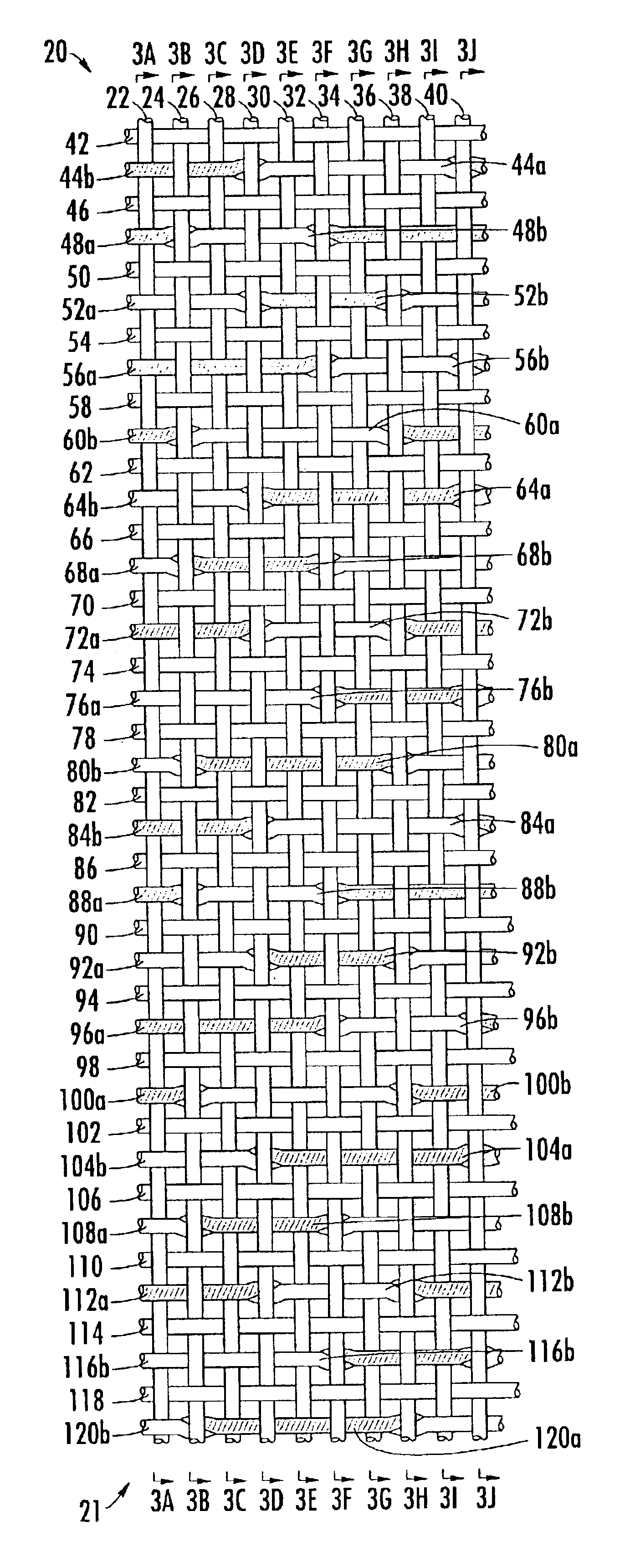
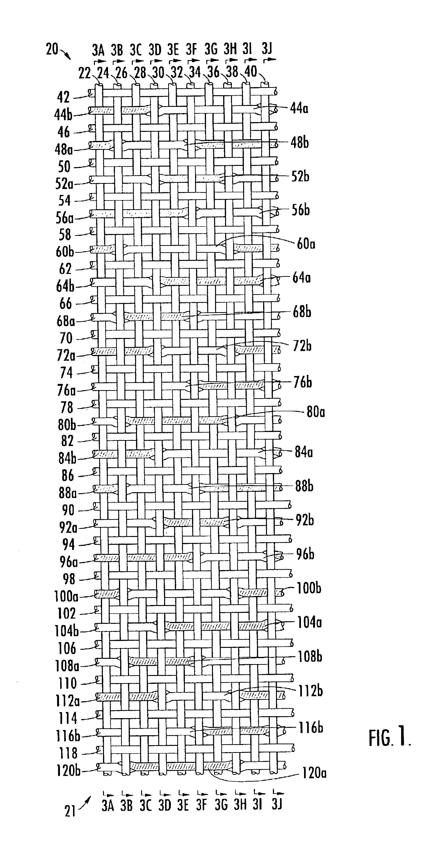
A twenty harness triple layer forming fabric 20 is illustrated in FIGS. 1-4, in which a single repeat unit of the fabric 20 is shown. The repeat unit of the fabric 20 includes a top layer 21 and a bottom layer 81. The top layer 21 includes ten top MD yarns 22, 24, 26, 28, 30, 32, 34, 36, 38 and 40 and twenty top CMD yarns 42, 46, 50, 54, 58, 62, 66, 70, 74, 78, 82, 86, 90, 94, 98, 102, 106, 110, 114, and 118. These are i...


PUM


Abstract

The bottom machine direction yarns and the bottom cross machine direction yarns of a triple layer fabric are interwoven in a series of repeat units in which the bottom machine direction yarns pass below multiple nonadjacent bottom cross machine direction yarns to form bottom machine direction knuckles, and in which pairs of bottom machine direction yarns separated from one another by one bottom machine direction yarn form bottom machine direction knuckle pairs under a common bottom cross machine direction yarn. Each bottom machine direction knuckle pair forms two imaginary diagonal lines with a nonadjacent bottom machine direction knuckle pair such that each bottom machine direction knuckle pair in the diagonal lines is offset by two cross machine direction yarns and one bottom machine direction yarn.

Description

FIELD OF THE INVENTIONThis invention relates generally to woven fabrics, and relates more specifically to woven fabrics for papermakers.BACKGROUND OF THE INVENTIONIn the conventional fourdrinier papermaking process, a water slurry, or suspension, of cellulosic fibers (known as the paper “stock”) is fed onto the top of the upper run of an endless belt of woven wire and / or synthetic material that travels between two or more rollers. The belt, often referred to as a “forming fabric”, provides a papermaking surface on the upper surface of its upper run which operates as a filter to separate the cellulosic fibers of the paper stock from the aqueous medium, thereby forming a wet paper web. The aqueous medium drains through mesh openings of the forming fabric, known as drainage holes, by gravity alone or with assistance from one or more suction boxes located on the lower surface (i.e., the “machine side”) of the upper run of the fabric.After leaving the forming section, the paper web is tr...

Claims


Application Information

Patent Timeline
IPC IPC(8): D21F1/00
CPCD21F1/0045Y10S162/903Y10T442/3195Y10T442/3179
Inventor TROUGHTON, BRIANBARRATTE, CHRISTINEBAUMANN, OLIVER
Owner WEAVEXX
Why Eureka
Try Eureka