Hybrid riser configuration

a riser configuration and hybrid technology, applied in the direction of bulkheads/piles, non-electric welding apparatus, fluid removal, etc., can solve problems such as relative deformation, and achieve the effect of reducing cost and risk exposur

Inactive Publication Date: 2005-01-04
AKER RISER SYST
View PDF28 Cites 82 Cited by
  • Summary
  • Abstract
  • Description
  • Claims
  • Application Information

AI Technical Summary

Benefits of technology

Objects of the present invention are to accommodate relative expansion of the riser tubes in a simple and reliable manner, and to reduce cost and risk exposure in connection with fabrication and installation of a hybrid riser configuration.
In accordance with the present invention, a hybrid riser configuration having a submerged tower comprises a plurality of riser pipes substantially inserted in guide conduits. The hybrid riser configuration also includes a buoyancy structure acting as a power tensioning structure. The riser pipes and guide conduits are connected to a base anchored to the ocean floor. A plurality of the guide conduits act as multiple tethers, with each guide conduit further acting as a radial constraint in elastic spiral deformation of the riser pipe inside. In accordance with one aspect of the present invention, during tow-out and insulation the guide conduits provide necessary buoyancy to make the riser configuration, except the base and buoyancy structure, nearly mutually buoyant.
The present invention also provides a method for installing a riser configuration having a submerged tower that comprises a plurality of riser pipes substantially inserted in guide conduits and also having a buoyancy tank and gravity base connected by the riser pipes and guide conduits. The method includes fabricating a bundle of guide conduits and riser pipes on a roller bed or rail bed from which it can be launched, connecting the buoyancy tank and gravity base to opposite ends of the bundle, sealing at least a plurality of the guide conduits and riser pipes of the bundle, launching the resultant structure and connecting the buoyancy tank and gravity base ends of the structure to respective towing vessels via towing wires, flooding the buoyancy tank to provide it with substantial negative buoyancy so that both the tank and the base will act as clump weights, towing the structure to the offshore location for its installation as a sub-surface tow while maintaining sufficient angle and tension in the towing wires to maintain substantial tension in the pipe bundle, lowering the base end of the structure by paying out the towing wire connected to the base, permitting water to enter the spaces formed between the riser pipes and their respective guide conduit when the base has reached a predetermined depth in order to limit the differential pressure across the wall of the guide conduits, continuing to lower the base end of the structure until the structure is perpendicular and suspended from the towing wire connected to the buoyancy tank, and lowering the structure to allow the base to penetrate the bottom mud-line and anchor the base to the ocean floor, and removing the water ballast and towing wire from the buoyancy tank, thus providing tension in the guide conduits.

Problems solved by technology

The challenge of such designs is to accommodate the relative deformation between the central tether and the risers.
The risers are subjected to temperature, internal pressure, and lateral deflection, which give rise to relative deformation.

Method used


Image

  • Hybrid riser configuration
  • Hybrid riser configuration
  • Hybrid riser configuration

Examples


Embodiment Construction

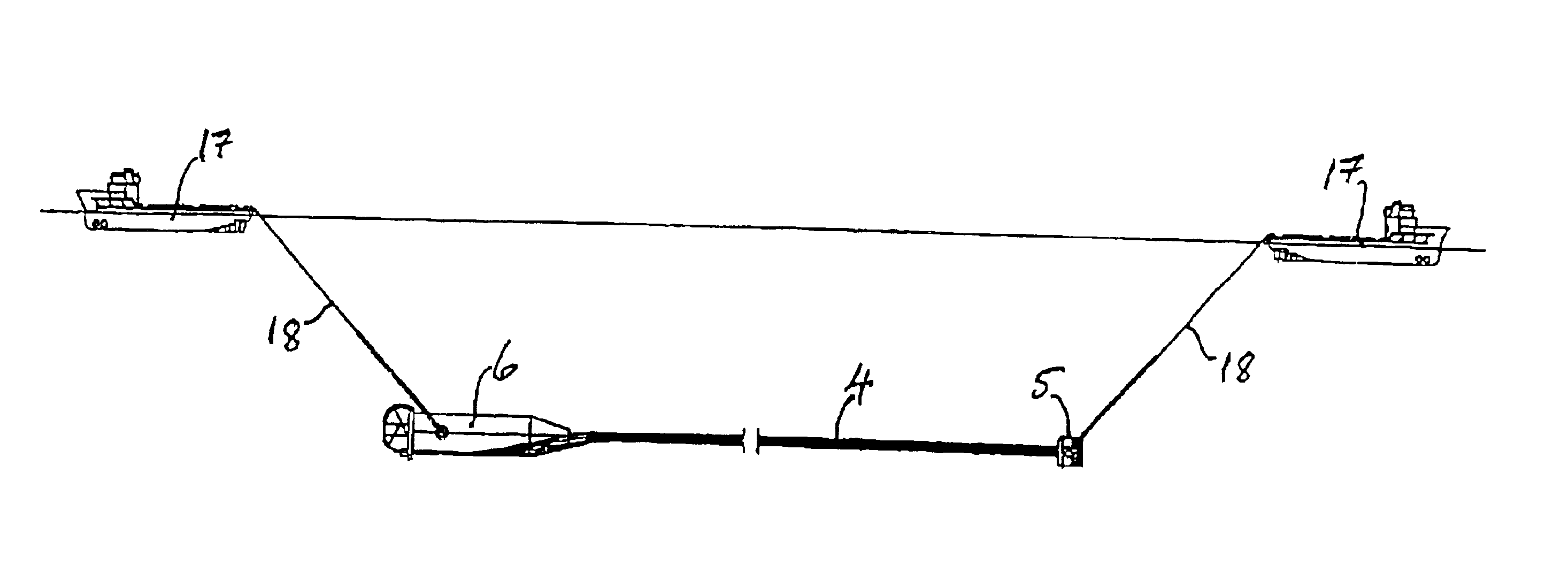
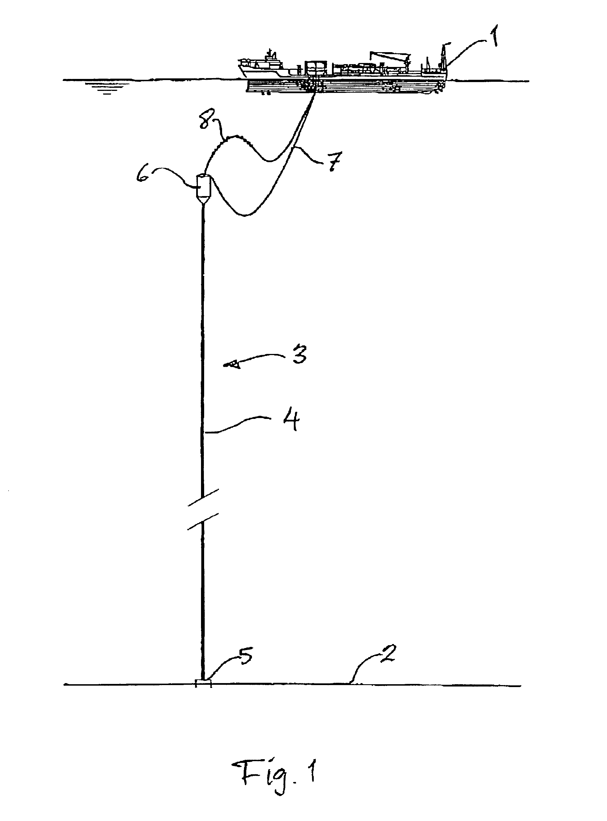
Referring to the drawings, FIG. 1 shows a surface vessel 1, e.g. a production ship for crude oil, connected to equipment (not shown) on the ocean floor 2 through a hybrid riser generally designated 3 and embodying the present invention. The riser 3 comprises a riser tower 4 connected at its lower end to a base 5 at the ocean floor 2 and at its upper end to a so-called soft tank buoyancy means 6 keeping the riser tower 4 in sufficient tension to avoid global buckling thereof.

At the buoy 6 the multiple risers of the tower 4 are connected to flexible jumper hoses 7, 8, the jumpers 7 carrying produced crude oil to the production ship 1 and the jumpers 8 carrying treated product from the ship 1 to an oil export system.

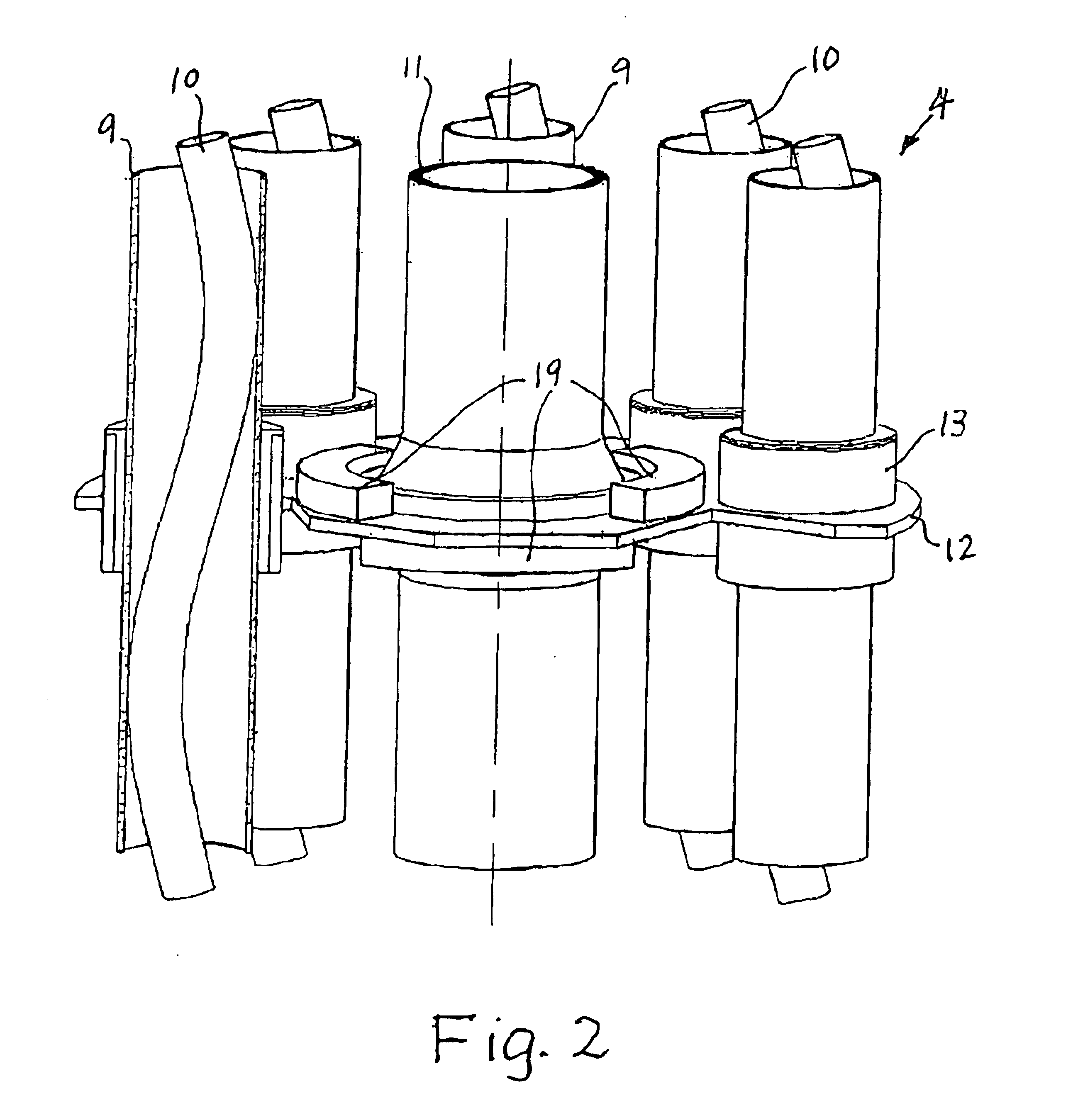
Details of the riser tower 4 are shown in FIGS. 2 and 3, FIG. 3 showing the lower part of the tower connected to the base 5 and FIG. 2 showing a section of the tower, e.g. somewhat like the upper part in FIG. 3, partly broken away and partly in cross-section.

The tower compr...


PUM

PropertyMeasurementUnit
diameteraaaaaaaaaa
diameteraaaaaaaaaa
buoyancyaaaaaaaaaa

Abstract

Hybrid riser configuration comprising a plurality of steel riser pipes substantially inserted in aluminium guide conduits, with buoyancy means and tethering tension means, the guide conduits and riser pipes being rigidly connected to a base anchored to the ocean floor. The guide conduits serve as the tethering tension means and as radial constraint for the respective riser pipe therein to allow the riser pipe to buckle in elastic deformation (Euler) to form a spiral when expanding due to service pressure and temperature. A method for installing the riser configuration is also disclosed.

Description

FIELD OF THE INVENTIONThe present invention relates to a hybrid riser configuration, primarily for offshore hydrocarbon services.BACKGROUND OF THE INVENTIONThe hybrid riser concept has developed from top tension risers. A principal feature is that it accommodates relative motion between a floating structure and a rigid metal riser by connecting them with flexible jumpers. The first hybrid riser installed, and so far the only, was a single riser anchored to the structure with a tensioned cable. Current concepts mainly involve multiple risers with tension provided by submerged buoyancy anchored by a tether.A principal advantage of hybrid risers tensioned by submerged buoyancy is that they are much less exposed to wave-induced cyclic loads and are not excited significantly by vessel motion either. The challenge of such designs is to accommodate the relative deformation between the central tether and the risers. The risers are subjected to temperature, internal pressure, and lateral def...

Claims


Application Information

Patent Timeline
Patent Type & Authority Patents(United States)
IPC IPC(8): B23K20/12E21B17/00E21B17/01
CPCB23K20/122E21B17/015E21B17/012
Inventor SELE, ARNENYGARD, MAGNE
Owner AKER RISER SYST
Why Eureka
Try Eureka