
Ink feed unit for ink jet recorder and diaphragm valve

a technology of ink jet recorder and diaphragm valve, which is applied in printing and other directions, can solve the problems of high accuracy and inability to accurately form the bending portion that affects the elasticity of the membrane valve, and achieve the effect of stably providing the recording head and being ready to manufactur

Inactive Publication Date: 2005-01-04
SEIKO EPSON CORP
View PDF15 Cites 34 Cited by
  • Summary
  • Abstract
  • Description
  • Claims
  • Application Information

AI Technical Summary

Benefits of technology

Hereby, the influence produced when the thick portion is injection molded at the periphery is removed, and the membrane valve can keep its posture stable in relation to the external force while it is corresponding to the very small differential pressure, so that there is an effect in which an ink supply unit that supplies ink to a recording head while it is maintaining the proper negative pressure can be readily manufactured.
Further, since a recess portion for bending does not exit around the membrane portion and the shape of the membrane valve is smooth as a whole, air bubbles do not stay, so that there is an effect in which the ink can be stably supplied to the recording head.

Problems solved by technology

However, it is very difficult to constitute the membrane valve that can correspond to the very small change of pressure produced by the ink consumption in the recording head, and does not open or close uselessly according to the vibration with a recording operation.
However, since it is necessary for this membrane valve to simultaneously form a frame portion having a large section which functions as a support portion at its periphery, there is a disadvantage in that it is necessary to be skilled in constituting at a high accuracy the bending portion that affects elasticity of the membrane valve greatly.

Method used


Image

  • Ink feed unit for ink jet recorder and diaphragm valve
  • Ink feed unit for ink jet recorder and diaphragm valve
  • Ink feed unit for ink jet recorder and diaphragm valve

Examples


Embodiment Construction

The invention will be described below in detail with reference to the shown embodiments.

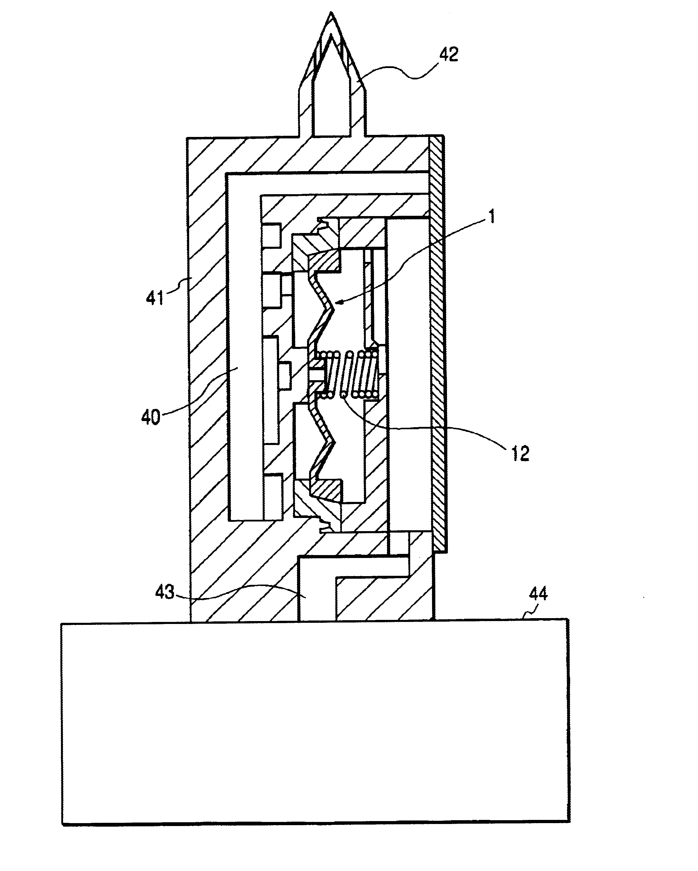
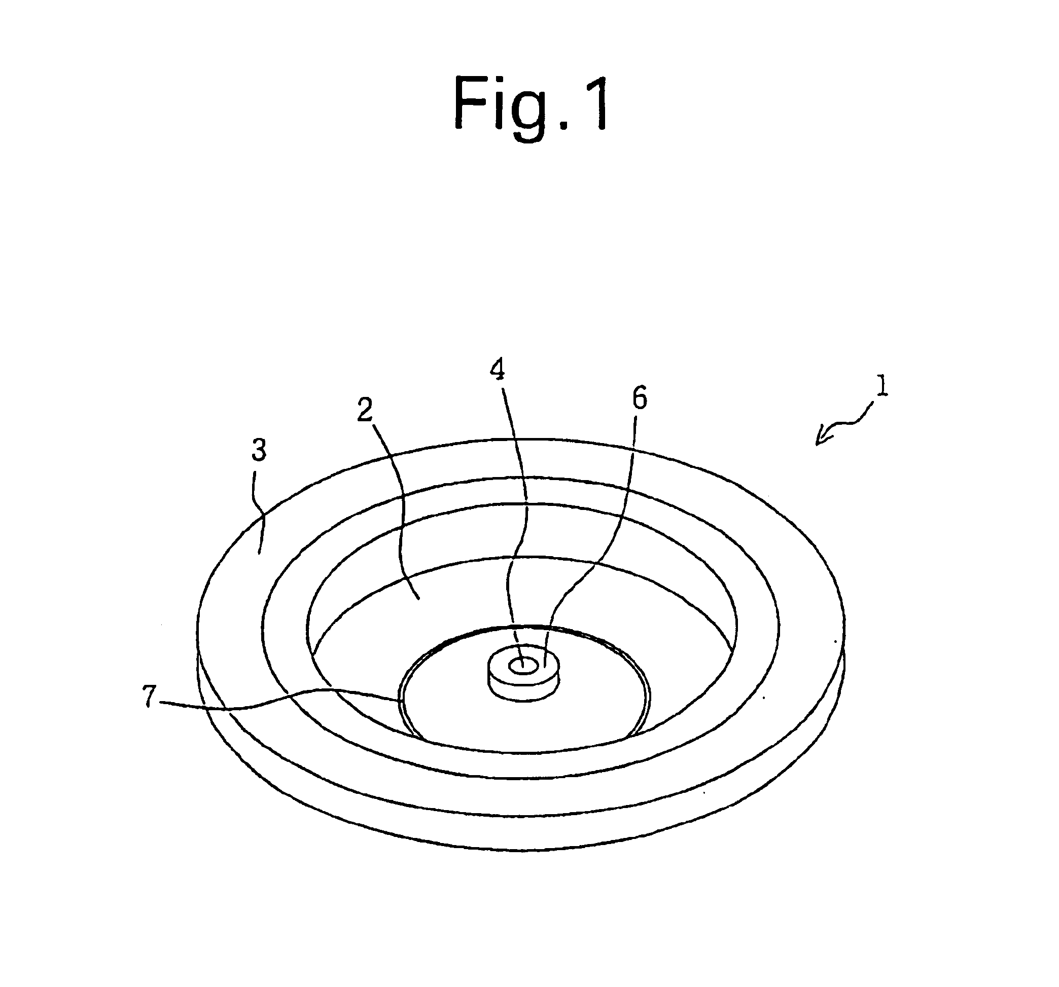
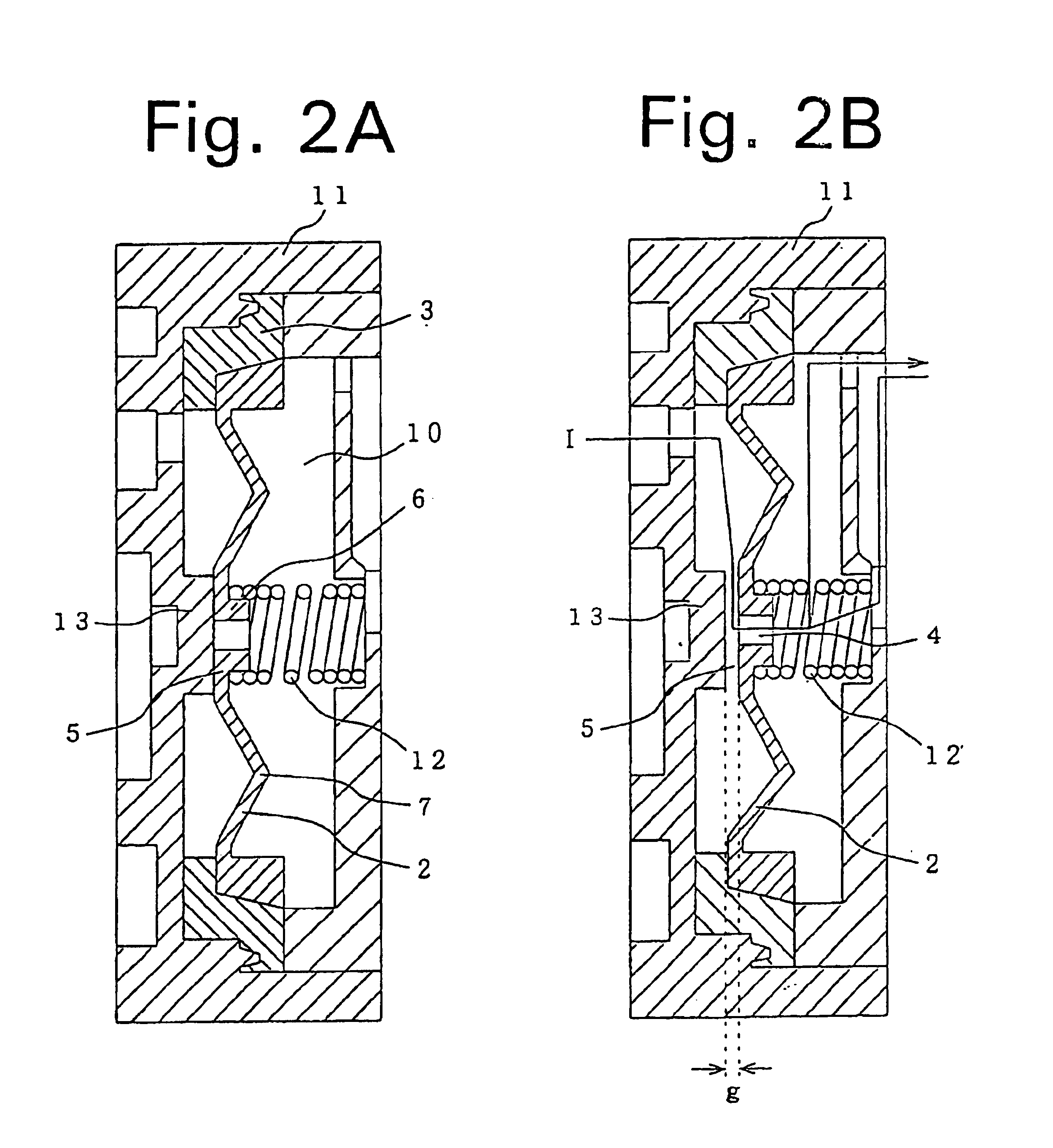
FIG. 1 shows one embodiment of a membrane valve of the invention, and FIG. 2 shows a valve closing state and a valve opening state in case where this membrane valve is built in a differential pressure valve mechanism. A membrane valve 1 constituted as a movable membrane comprises a membrane portion 2 which is formed of soft material that can deform elastically upon reception of the differential pressure, and a thick frame portion 3 which is formed of hard material that supports the periphery of the membrane portion 2 and is clamped and held by a fixing member such as a casing, which are integrally manufactured preferably by two color molding of a polymer.

In the membrane portion 2, an ink passing port 4 is formed in its center, a region 5 opposed to a valve seat is formed as an approximately flat surface, and a spring receiving protrusion 6 having a circular section is formed on the other surface....


PUM


Abstract

An angled portion that is concentric with respect to an ink passing port (4) is formed in a central region (7) of a membrane portion (2) to function as an elasticity providing portion, whereby the influence produced when a thick portion is injection molded at the periphery is removed from affecting elasticity of a membrane valve.

Description

TECHNICAL FIELDThe present invention relates to an ink supply unit that supplies ink in an ink cartridge to an ink jet recording head in a state where a constant negative pressure is applied onto the ink.BACKGROUND ARTAn ink jet recording apparatus used in a large number of printers adopts such an ink supply structure that an ink cartridge such as a cassette is put in a casing member, the ink cartridge is connected through an ink supply tube to an ink supply unit mounted on a carriage, and ink consumed in printing is supplied to a recording head through the ink supply unit including a differential pressure valve mechanism comprising a membrane valve.By adopting this structure, according to the amount of ink consumption in the recording head, ink can be supplied to the recording head by opening and closing of the membrane valve.However, it is very difficult to constitute the membrane valve that can correspond to the very small change of pressure produced by the ink consumption in the...

Claims


Application Information

Patent Timeline
IPC IPC(8): B41J2/175
CPCB41J2/17596B41J2/175
Inventor USUI, MINORU
Owner SEIKO EPSON CORP
Learn More