Modular barrier

a module and barrier technology, applied in the field of modules, can solve problems such as gap tripping hazards, and achieve the effects of preventing the continued articulation of the barrier section, and increasing the resistance of the barrier to lateral impact forces

Inactive Publication Date: 2005-01-04
RLT DESIGN
View PDF18 Cites 24 Cited by
  • Summary
  • Abstract
  • Description
  • Claims
  • Application Information

AI Technical Summary

Benefits of technology

When a plurality of barrier sections according to the invention and hinge pins are assembled into a modular barrier, the projections on a female end of a first barrier section mate with the projections on a male end of another barrier section and a hinge pin passes through them and through the nose of the first barrier section, to articulate the sections together. For traffic control purposes, the plurality of reinforcing strips are attached to their respective barrier sections, to continue to permit them to be articulated together whilst increasing the resistance of the barrier to lateral impact forces.
In a preferred implementation, the plurality of reinforcing strips are also able to be attached to their respective barrier sections and adjacent barrier sections, to prevent continued articulation of the barrier sections whilst increasing the resistance of the barrier to lateral impact forces.
To secure the hinge pin in place, it may have a male thread that engages with a female thread in a dome-shaped cap, the nose of the first barrier section having a dome-shaped recess to accommodate the cap. The dome-shaped cap can be bolted down to the ground before the barrier is erected. The cap and the recess are dome-shaped so that, although the spacing between adjacent caps is critical, their relative orientation is not, making their installation a much simpler proposition.
Further strength can be imparted to the assembled barrier if the barrier sections are also held together by tension straps that encircle adjacent barrier sections, crossing from one side of the barrier to the other between the barrier sections. These can spread impact forces across a number of adjacent barriers. For ease of installation of the straps, the upright portion of each barrier section may be provided with grooves to accommodate them.

Problems solved by technology

The same problem exists with barriers used for crowd control, except the gap is a tripping hazard.

Method used


Image

  • Modular barrier
  • Modular barrier
  • Modular barrier

Examples


Embodiment Construction

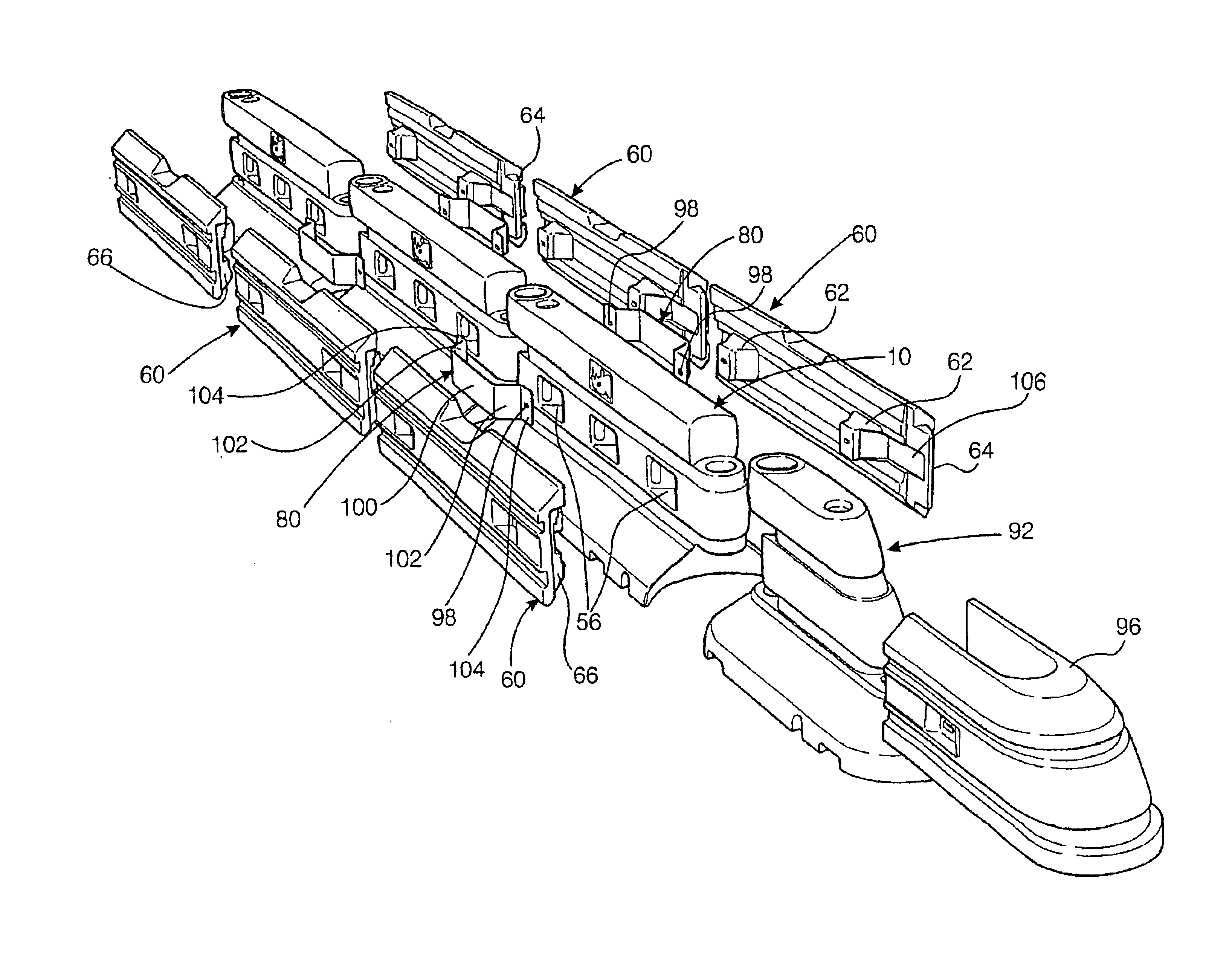
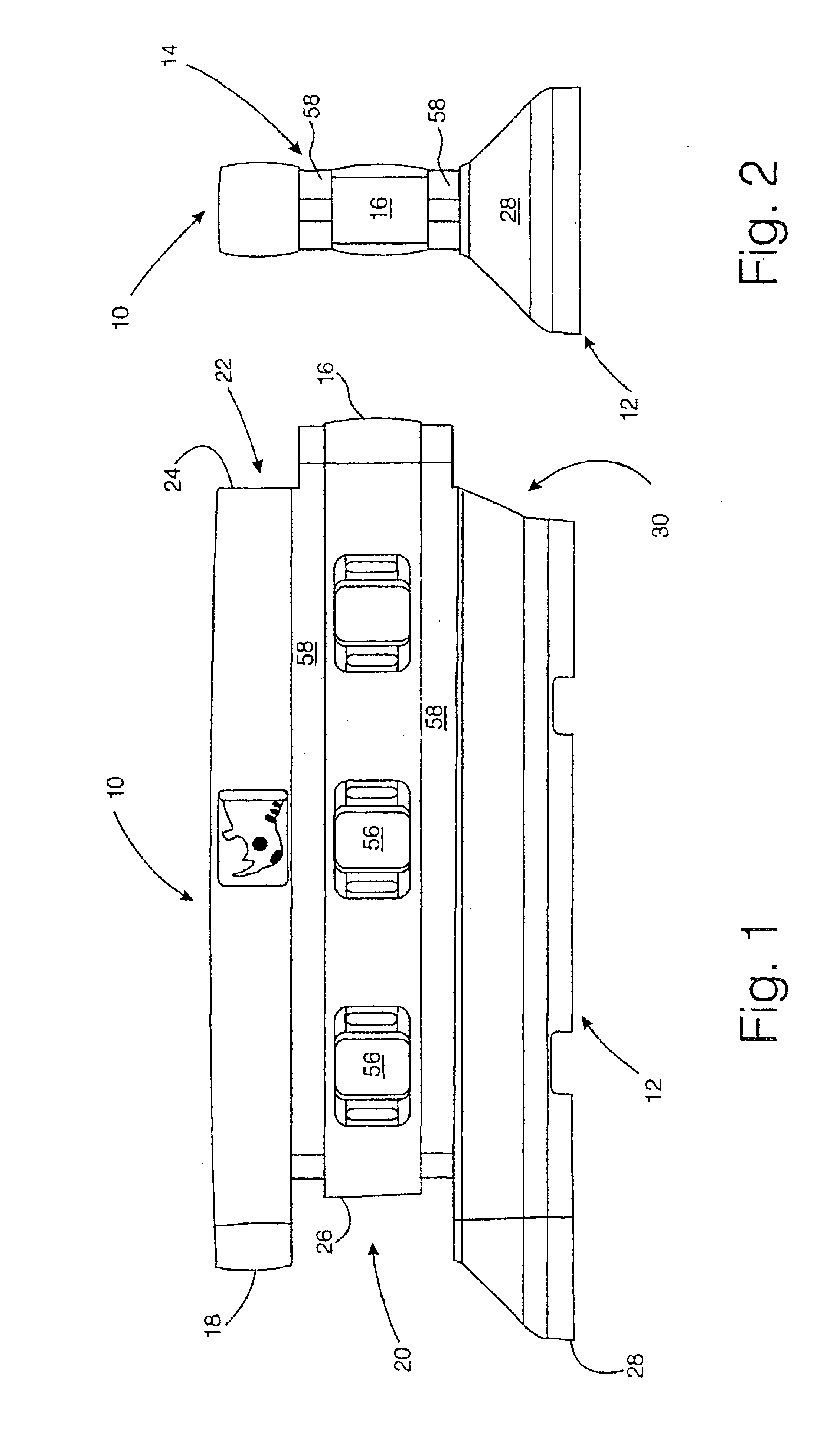
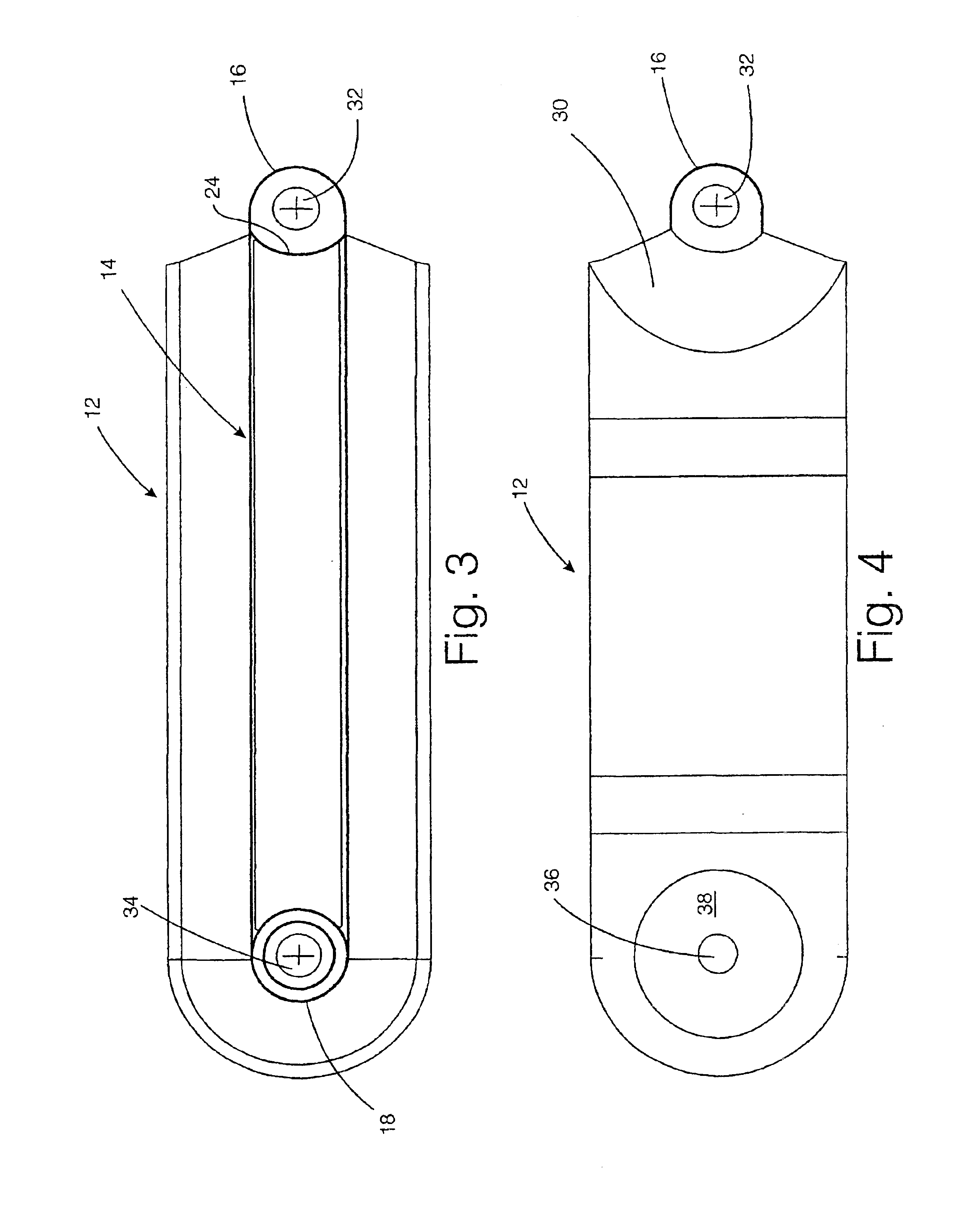
FIGS. 1 and 2 show a barrier section 10 that is formed by rotation moulding from high-density polyethylene. Because the barrier section is rotation moulded, it is hollow and can be filled with water when in use for traffic control. To that end it is provided with a filling port and a drain plug (not shown). The barrier section includes a comparatively wide base portion 12 surmounted by a comparatively narrow upright portion 14. The upright portion has a first projection 16 at a male end of the barrier section and a second projection 18 at the female end. As is more clearly shown in FIG. 3, when considered in conjunction with FIGS. 1 and 2, both projections have substantially semicylindrical outer surfaces. The first projection 16 is designed to fit into a correspondingly shaped first recess 20 that lies below the second projection 18 of a similar barrier section. The second projection 18 is designed to fit into a correspondingly shaped second recess 22 that lies above the first proj...


PUM


Abstract

A modular barrier includes a plurality of substantially identical barrier sections each section having a base portion surmounted by an upright portion. The upright portion has projections with substantially semi-cylindrical outer surfaces at its ends. Correspondingly shaped recesses are also provided. At a femal end, the base portion includes a nose. The surface of the nose is a surface of rotation of the profile of the base portion. At the male end, the base portion includes a correspondingly shaped cavity. The first and second projections and the nose are provided with bores. When the female end of the barrier section is brought up to a male end of a similar, adjacent barrier section, the projections mate with one another and the nose is received in the cavity of the adjacent barrier section. A hinge pin may then be passed through the bores for allowing one barrier section to be articulated to an adjacent barrier section with the joint between the two portions of adjacent barrier sections presenting an essentially smooth profile irrespective of the angle between the two adjacent barrier sections.

Description

BACKGROUND TO THE INVENTIONThis invention relates to modular barriers of the type used in crowd and traffic control.Conventional modular traffic control barriers consist of a number of barrier sections made from cast concrete. Each barrier section has a comparatively narrow upright portion surmounted by a comparatively wide base portion. Metallic ties are cast into the concrete and project from both ends of the upright portion of the barrier section. When two barrier sections are placed side-by-side, the metallic ties line up and can be bolted through, thus attaching the barrier sections to one another and at the same time forming a makeshift hinge. By means of the hinge, the two barrier sections can be articulated relative to one another, allowing the completed barrier to follow a serpentine path if desired.Similar designs are in use for crowd control barriers. An example is described in U.S. Pat. No. 5,836,714. The barrier in question is particularly well illustrated in FIG. 9 of ...

Claims


Application Information

Patent Timeline
Patent Type & Authority Patents(United States)
IPC IPC(8): E01F15/00E01F13/02E01F15/02E01F15/08E01F15/14E01F13/00
CPCE01F13/022E01F15/088E01F15/086
Inventor TAGG, RICHARD LEACH
Owner RLT DESIGN
Why Eureka
Try Eureka