Power supply switch of motor vehicle

a technology of power supply switch and motor vehicle, which is applied in the direction of coupling contact member, coupling device connection, incorrect coupling prevention, etc., can solve the problem of absorbing force at the abutment of the connector, and achieve the effect of improving the reliability of electrical connection

Inactive Publication Date: 2005-01-04
YAZAKI CORP
View PDF2 Cites 13 Cited by
  • Summary
  • Abstract
  • Description
  • Claims
  • Application Information

AI Technical Summary

Benefits of technology

Preferably, a forward end of the pin tab terminal is located rearward from the front surface of the terminal cover piece during a disengaged state of the base body side connector and the movable body side connector. Thereby, the tab terminal is not exposed in a state where the base body and movable body side connectors are disengaged, for example, when a back door of the vehicle is open. Thus, the tip of the tab terminal will not be harmful to a passenger of the vehicle.
Preferably, the housing is unitarily formed with another flange at an inner wall thereof for abutting against the flange of the terminal cover piece. Thereby, the terminal cover piece flange abuts against the stopper flange of the connector housing to limit a further advance of the terminal cover piece in the tab terminal insertion direction, while the tab terminal is received in the terminal cover piece not to extend therefrom. The terminal cover piece slides since an outer side surface of the terminal cover piece is slidable for the flange of the connector housing. Thus, the front surface of the terminal cover piece can stop at a predetermined position so that the terminals can reliably contact with each other. The terminal cover piece can slide in a stable state.
Preferably, a resilient member is fitted with a rear end of the tab terminal such that the resilient member urges the tab terminal in an insertion direction of the tab terminal. Thereby, the tab terminal is urged by the resilient member, so that the resilient member is compressed to absorb an impact force for the tab terminal when an unintentional external force is exerted on the tab terminal. Thus, a further improvement of reliable electrical connection thereof is achieved.

Problems solved by technology

Furthermore, the impact force at the abutment of the connectors is absorbed, maintaining a contact reliability thereof for a long time.

Method used


Image

  • Power supply switch of motor vehicle
  • Power supply switch of motor vehicle
  • Power supply switch of motor vehicle

Examples


Embodiment Construction

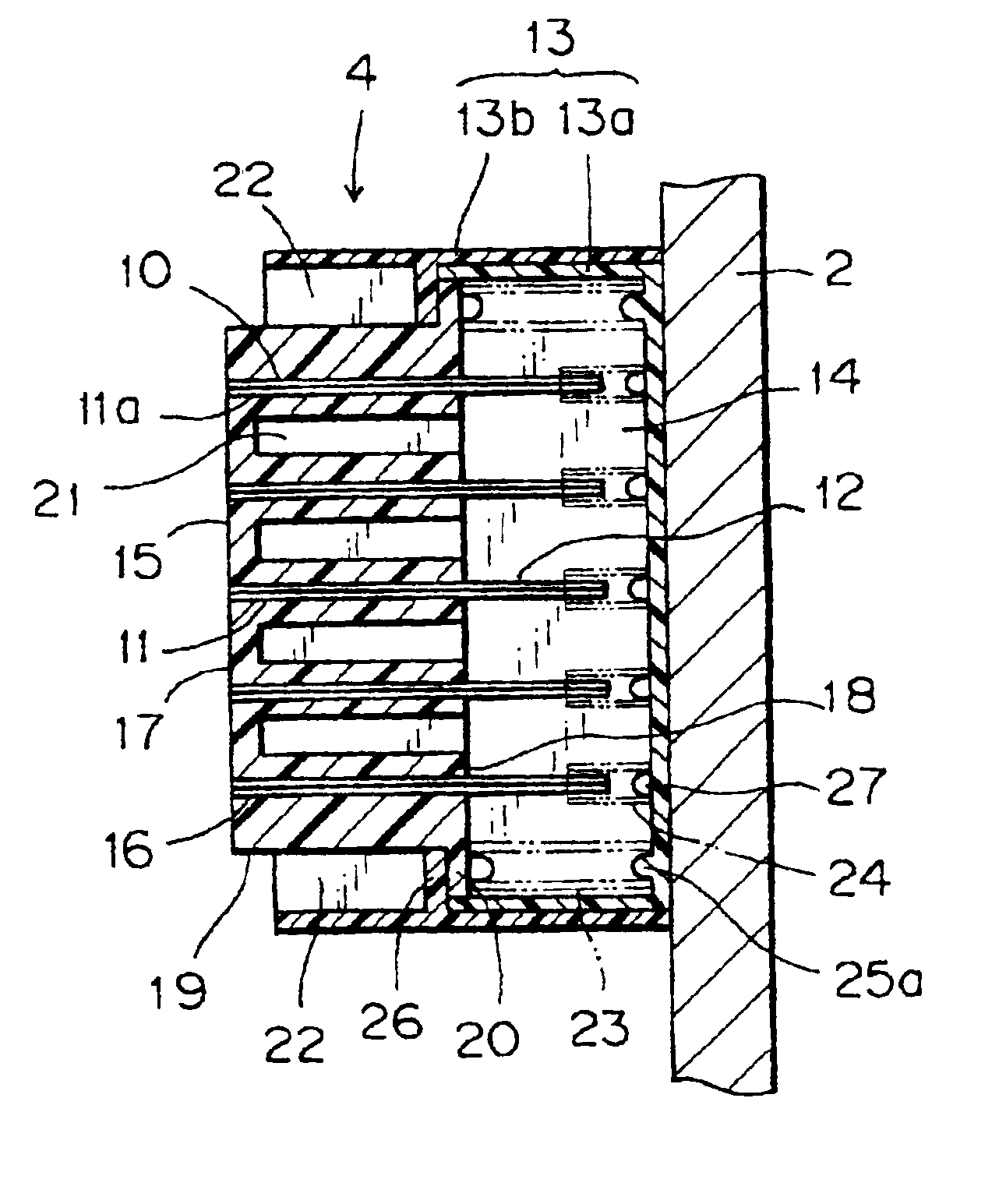
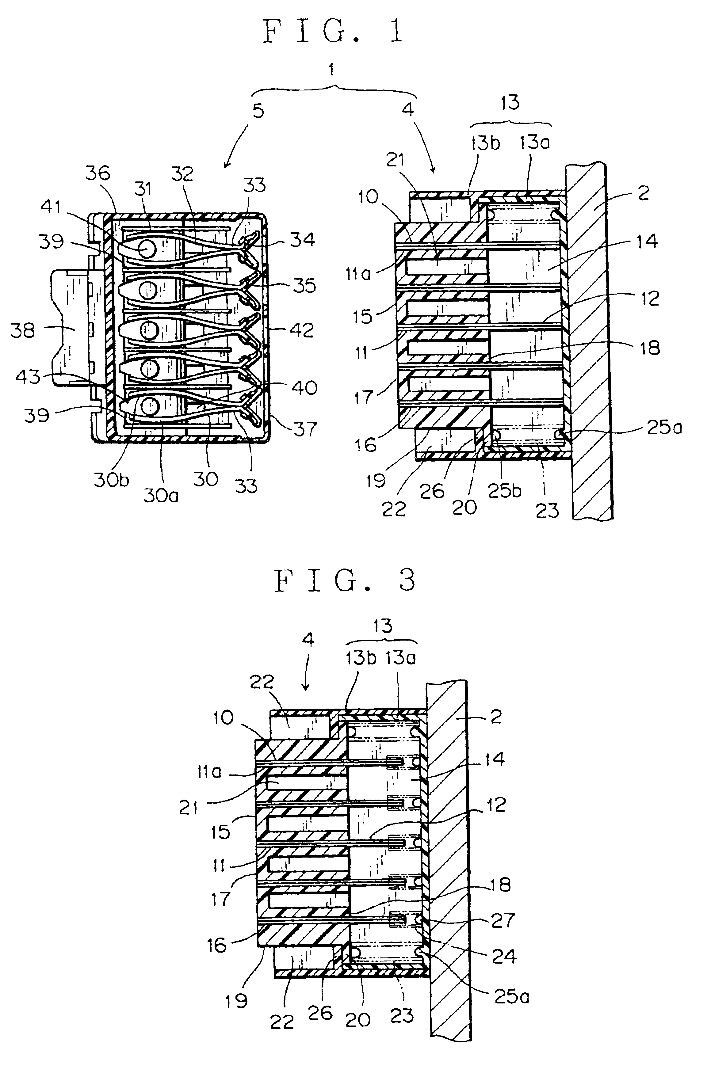
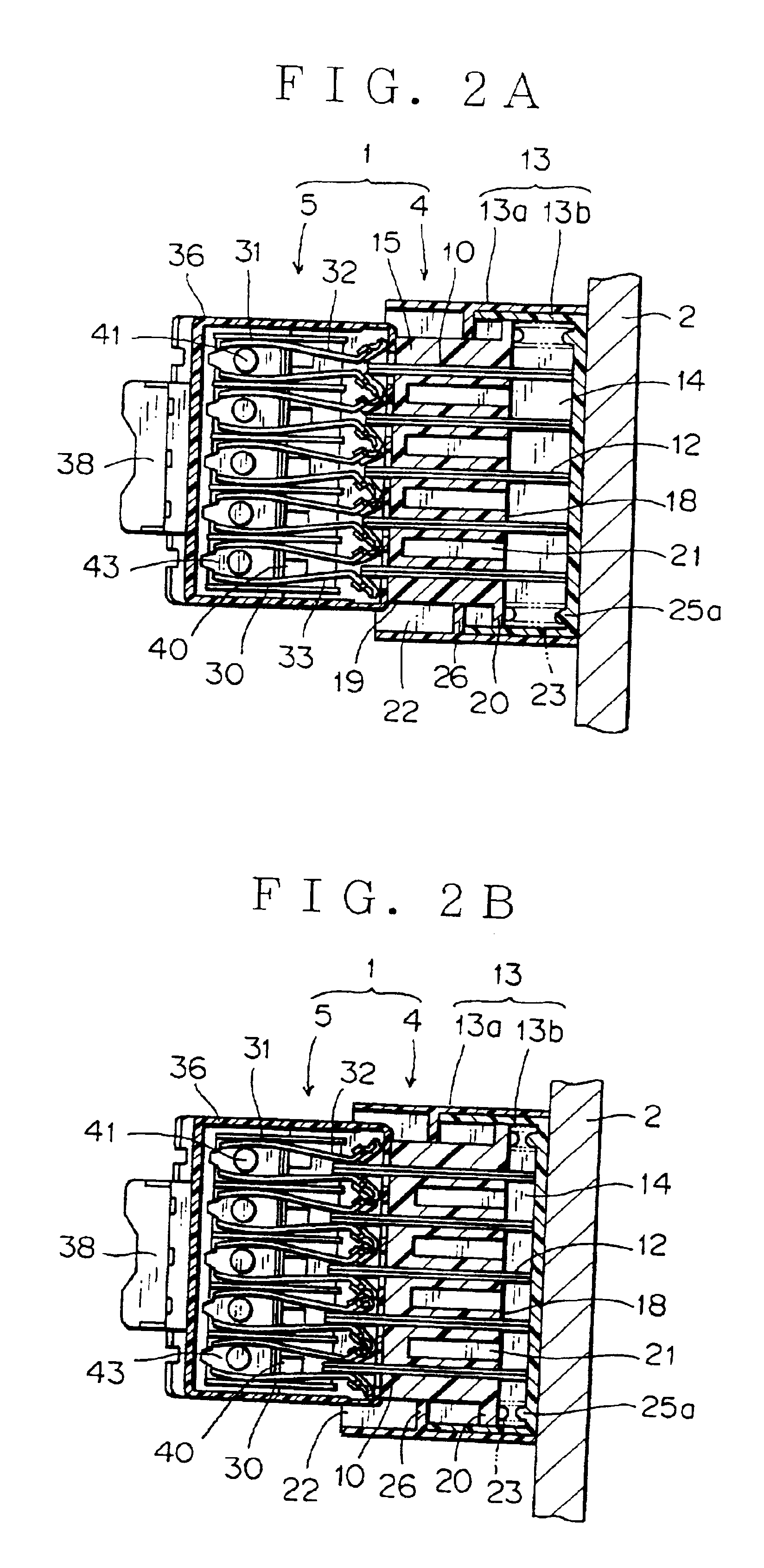
Referring to the accompanied drawings, embodiments of the present invention will be discussed in detail. FIGS. 1 and 2 shows a first embodiment of a power supply switch of the present invention.

A motor vehicle has a door panel 2 provided with a movable body side connector 4. The movable body side connector 4 is constituted by a housing 13 having a fore end opening space 22, a plurality of tab terminals 10 received in an inner space 14 of the housing 13, and a terminal cover piece 15 accommodating a forward half 11 of each tab terminal 10 to protect it.

The housing 13 has a longitudinally U-shaped cover 13a and a case 13b engaged with the cover 13a. In this embodiment, the cover 13a and the case 13b are formed in separate bodies, which is easy in molding thereof. However, they may be unitarily formed. The cover 13a and the case 13b are made of an insulating synthetic resin material.

The tab terminals 10 are spaced in parallel from each other. Like a cantilever beam, the tab terminal 10...


PUM


Abstract

The switch includes a base body side connector and a movable body side connector for connecting electrical circuits provided in a base body side and a movable body side of a motor vehicle. One of the base body side connector and the movable body side connector has a receptacle terminal while the other has a pin tab terminal. The other connector has a terminal cover piece for receiving an electrical contact portion provided in a free end side of the pin tab terminal. The terminal cover piece is slidable in engagement and disengage directions of the terminals. The terminal cover piece is urged by a resilient member parallel to an extended direction of the pin tab terminal. The resilient member is positioned between a flange of the terminal cover piece and a bottom surface of a housing of the movable body side connector.

Description

BACKGROUND OF THE INVENTION1. Field of the InventionThe present invention relates to a power supply switch of an auxiliary apparatus located a back door or a slide door of a vehicle like a motor vehicle for electrical connection to a power source of a base body side of the vehicle.2. Related ArtA motor vehicle has various auxiliary apparatuses such as a rear wiper and a door lock located in a back door, a slide door, etc. For these apparatuses, various types of power supply switches have been proposed.FIG. 5 shows a prior-art power supply switch 51 of a motor vehicle which is disclosed in Japanese Patent Application Laid-open No. 2000-62545. In FIG. 5, reference numeral 53 designates a base body side connector, and 52 designates a movable body side connector.The base body side connector 53 has an insulating resin housing 71 and a plurality of receptacle terminals 65 adjacently parallel arranged in the housing 71. The housing 71 has an upper cover (not shown) and a lower cover (not s...

Claims


Application Information

Patent Timeline
Patent Type & Authority Patents(United States)
IPC IPC(8): H01R13/631H01R13/24H01R13/22H01R13/52
CPCH01R13/631H01R13/2421H01R2201/26
Inventor MIGIMATSU, YUJIKAWAHATA, KATSUAKISANO, HIROTAKE
Owner YAZAKI CORP
Why Eureka
Try Eureka