Method and apparatus for instrumenting a gas turbine component having a barrier coating

a technology of gas turbine engine and barrier coating, which is applied in the field of gas turbine engines, can solve the problems of damage to downstream parts of the engine, the inability of super alloy materials to withstand extended exposure to the hot combustion gas of the current generation gas turbine engine without, and the difficulty of obtaining real-world operating environment data

Inactive Publication Date: 2005-01-04
SIEMENS ENERGY INC
View PDF15 Cites 109 Cited by
  • Summary
  • Abstract
  • Description
  • Claims
  • Application Information

AI Technical Summary

Problems solved by technology

However, even super alloy materials are not able to withstand extended exposure to the hot combustion gas of a current generation gas turbine engine without some form of cooling and / or thermal insulation.
Such real world operating environment data is very difficult to obtain, particularly for components that move during the operation of the engine such as the rotating blades of the turbine.
Surface mounted sensors must withstand severe mechanical and thermal loads, and if they become dislodged, they may cause damage to downstream portions of the engine.
However, the patent does not describe how such sensors may be placed within the structure, and the functionality of the sensors is not intended for the high temperature, corrosive environment of a gas turbine engine.
However, they are not useful for instrumenting a component of a gas turbine engine that is covered with a layer of a thermal barrier coating material.

Method used


Image

  • Method and apparatus for instrumenting a gas turbine component having a barrier coating
  • Method and apparatus for instrumenting a gas turbine component having a barrier coating
  • Method and apparatus for instrumenting a gas turbine component having a barrier coating

Examples


Embodiment Construction

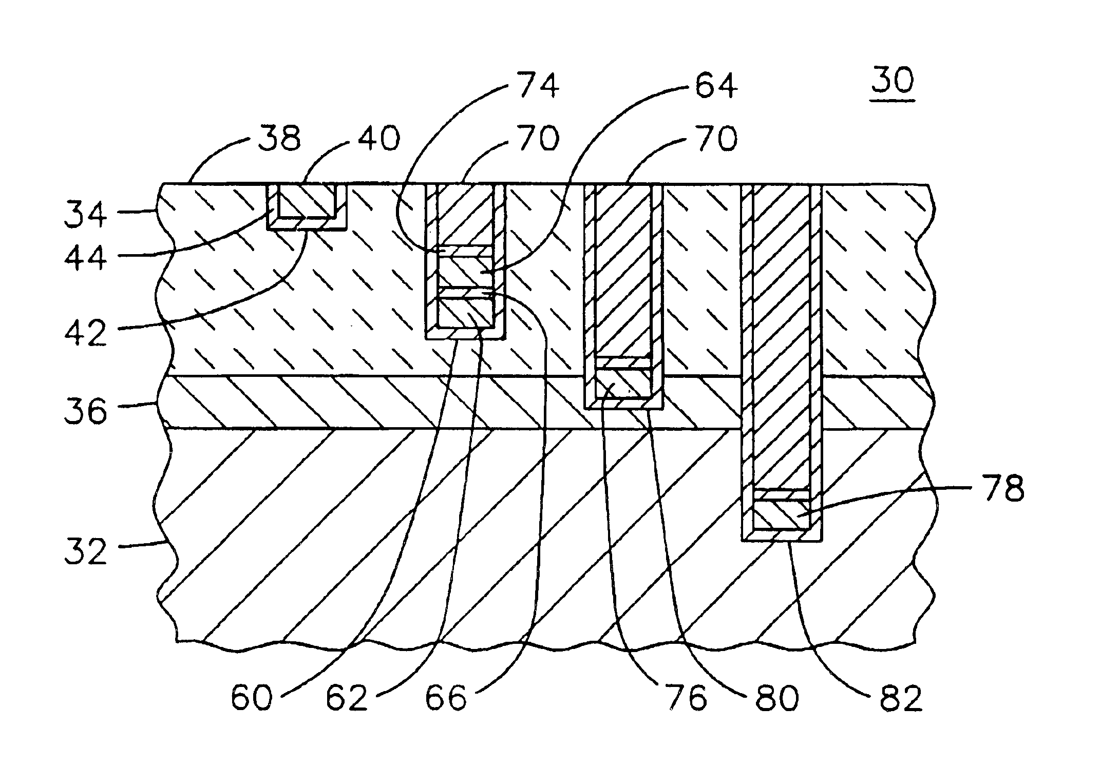
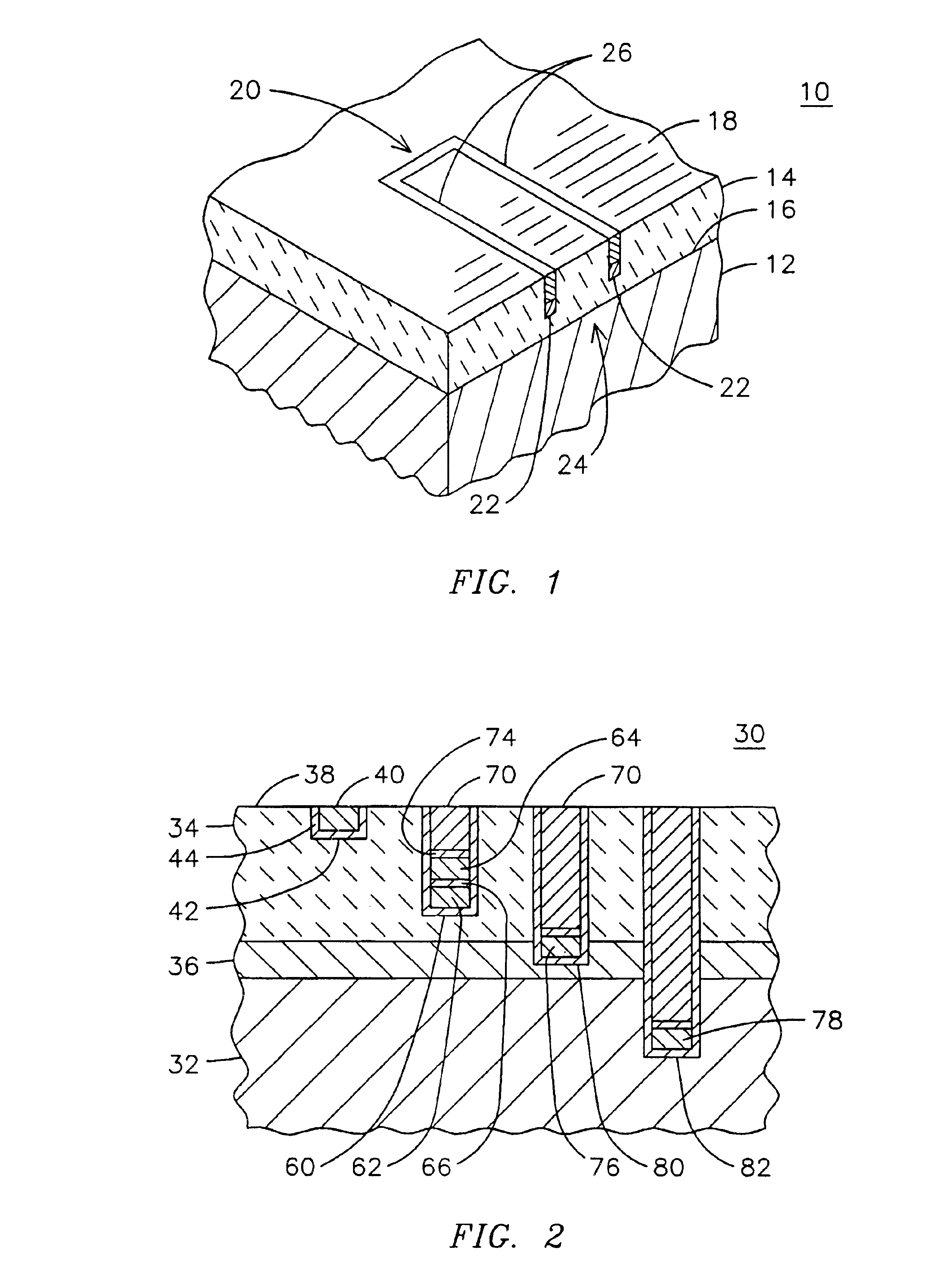
FIG. 1 is a partial perspective illustration of a component 10 formed of a substrate material 12 having a barrier coating such as a layer of thermal barrier coating (TBC) 14 disposed on one surface 16. The component 10 may be part of a gas turbine engine, for example, or any other machine wherein a base material must be protected from an external environment by a layer of a barrier material. In one embodiment, component 10 may be an airfoil member disposed in the hot gas flow path of a gas turbine engine with an oxide or non-oxide ceramic TBC 14 such as mullite, silicon carbide or a zirconium-based ceramic overlying a superalloy substrate material 12. Component 10 may alternatively be fabricated from a ceramic matrix composite (CMC) substrate coated with an environmental barrier coating (EBC). Because the integrity of the thermal barrier coating 14 is critical to the overall integrity of the component 10, it is useful to obtain operating parameter information that directly affects t...


PUM

PropertyMeasurementUnit
depthaaaaaaaaaa
widthaaaaaaaaaa
energyaaaaaaaaaa

Abstract

A method (50) of instrumenting a component (10) having a barrier coating (14). A sensor (76) is embedded within or below the coating. Material forming the sensor is deposited within a trench (80) formed into the barrier coating. The trench is then backfilled with material (70) to protect the sensor from the environment within which the component is operating. In this manner, the sensor may be embedded at any desired location and any desired depth within a barrier coating on a previously fabricated component. An array of sensors (98, 100, 102) may be embedded across the depth of the coating to provide signals indicative of operating conditions across the coating. The signals may be conducted to a connection location (24) by conductors (62, 64) that are deposited within the trench. The trench may be formed with a laser engraving process (54) and the material for the sensor and conductors may be deposited with a selective laser melting process (58).

Description

FIELD OF THE INVENTIONThe present invention relates to the field of gas turbine engines, and in particular to a method and apparatus for instrumenting a component of a gas turbine engine for monitoring the environment of a coating formed on a surface of the component.BACKGROUND OF THE INVENTIONFiring temperatures in modern gas turbine engines continue to increase in response to the demand for higher efficiency engines. Super alloy materials have been developed to withstand the corrosive high temperature environment that exists within a gas turbine engine. However, even super alloy materials are not able to withstand extended exposure to the hot combustion gas of a current generation gas turbine engine without some form of cooling and / or thermal insulation.Thermal barrier coatings are widely used for protecting various hot gas path components of a gas turbine engine. The reliability of such coatings is critical to the overall reliability of the machine. The design limits of such coat...

Claims


Application Information

Patent Timeline
Patent Type & Authority Patents(United States)
IPC IPC(8): C23C24/10C23C4/18C23C24/00C23C28/00F23M5/00F23R3/00F23M11/00
CPCC23C4/18C23C28/00F23M5/00F23M11/00F23R3/007C23C24/04G01N3/56Y10T428/12361Y10T428/2462Y10T428/12611Y10T428/26B33Y80/00Y10T428/249994
Inventor SUBRAMANIAN, RAMESH
Owner SIEMENS ENERGY INC
Why Eureka
Try Eureka