Thermofusible glue applicator with heating element track pressed against heating body

Inactive Publication Date: 2005-01-04
ISABERG RAPID
View PDF9 Cites 5 Cited by
  • Summary
  • Abstract
  • Description
  • Claims
  • Application Information

AI Technical Summary

Benefits of technology

Thus an object of the present invention is to provide a hot melt glue applicator that does not have the disadvantages referred to above and which in particular includes a heating body that is perfectly sealed with respect to the molten glue, the heating elements being very easy to install.
As explained in more detail later, by disposing the heating element(s) of the applicator in this way, excellent thermal contact is maintained between the elements and the mass of glue to be heated, through the thermally conductive material of the heating body, whilst eliminating the passage of the electrical power supply wires of the heating elements through the body, and thus any possibility of glue leaking. Furthermore, the position of the heating elements against the exterior surface of the heating body greatly facilitates their installation.

Problems solved by technology

This arrangement of the heating elements nevertheless has disadvantages.
Apart from the fact that they are inconvenient to install, supplying electrical power to them requires holes in the heating body for the power supply wires to pass through, which holes can give rise to leakage of the glue, especially if the wires also pass through the substrate of the heating element.
If the latter is made of metal, the passage of the wires further gives rise to problems of electrically insulating the wires from the substrate.

Method used


Image

  • Thermofusible glue applicator with heating element track pressed against heating body
  • Thermofusible glue applicator with heating element track pressed against heating body

Examples


Embodiment Construction

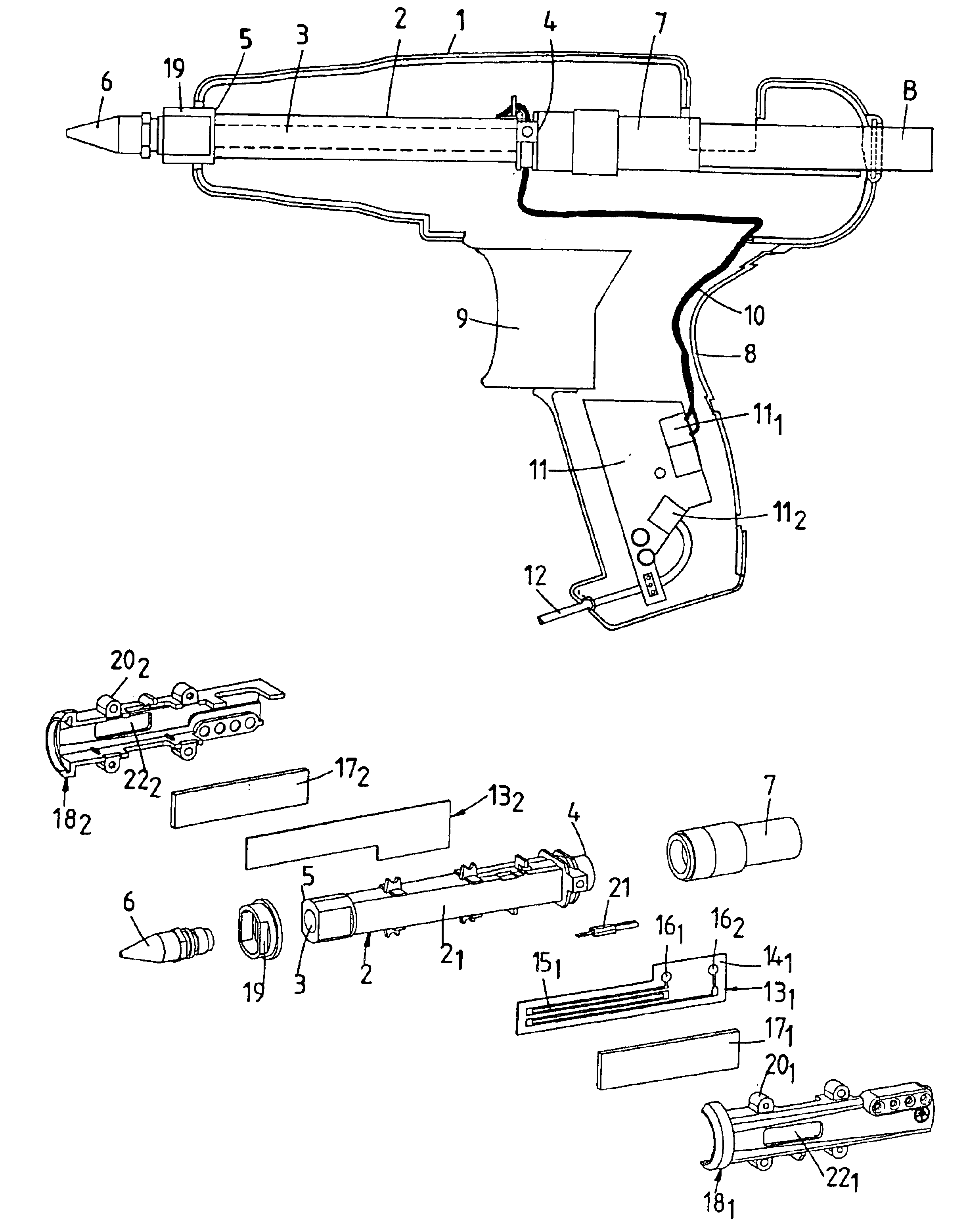
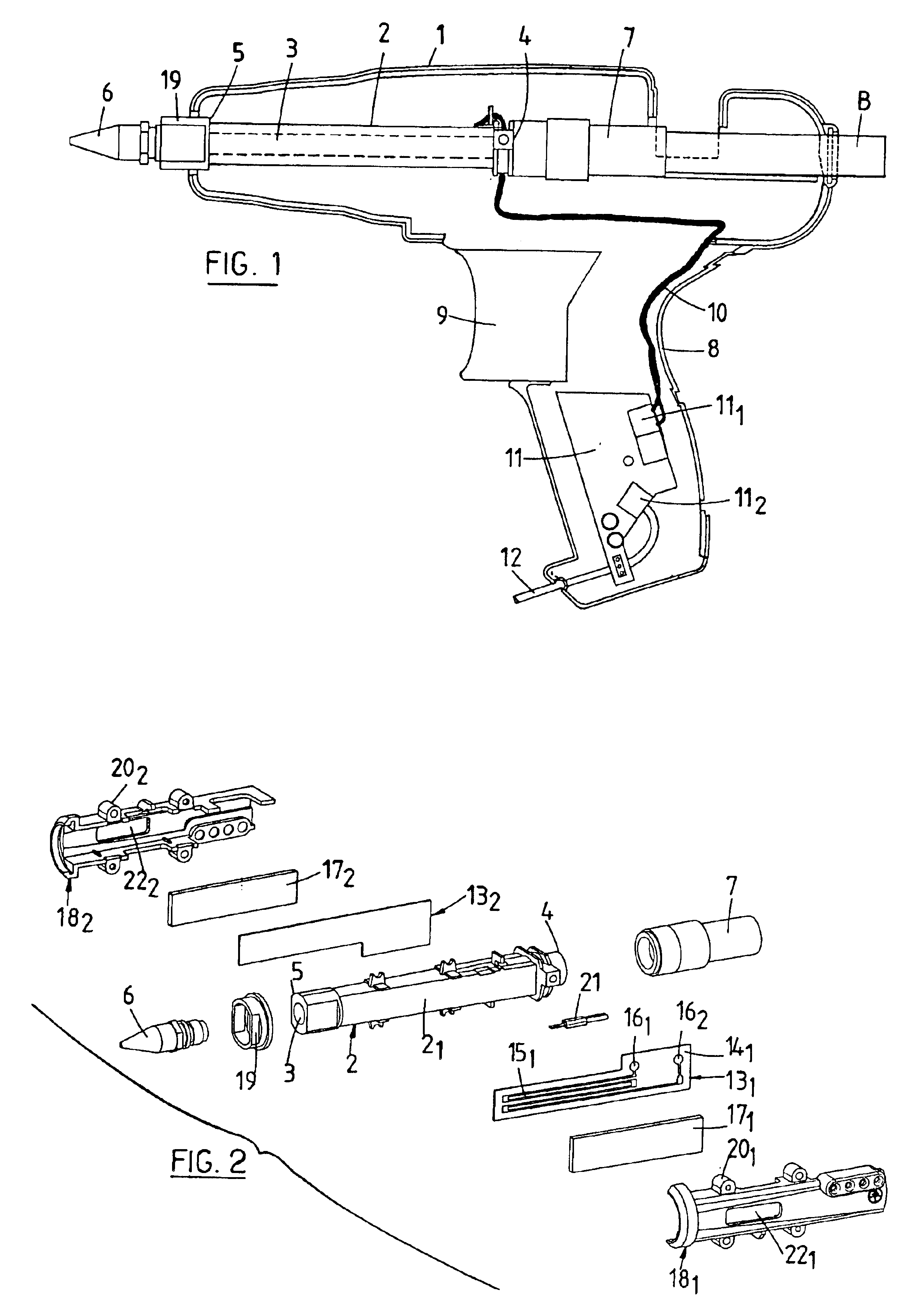
FIG. 2 shows the components shown in FIG. 1, namely the pierced heating body 2 of the chamber 3 extended at one end by the nozzle 6 and at the other end by the bush 7.

The heating body 2 has an exterior surface conformed to receive, in intimate contact with it, two heating elements 131, 132 on two opposite plane facets 21, 22 of the exterior surface (only the facet 21 can be seen in FIG. 2). An interior surface of the heating body delimits the chamber 3.

The two heating elements are identical and each comprises a substrate 141, 142 with at least one face covered by a screenprinted track, such as the track 151 visible on the substrate 141 of the heating element 131.

The heating elements are of the type described in the U.S. patent previously cited, formed of a plane substrate on which is screenprinted a resistive paste or “ink” tracing the track 151, using the technology employed for fabricating thick film hybrid circuits. Reference may also be made to the U.S. patent previously cited f...


PUM

PropertyMeasurementUnit
Temperatureaaaaaaaaaa
Massaaaaaaaaaa
Electrical conductoraaaaaaaaaa

Abstract

The invention relates to an applicator comprising a) an elongated chamber (3) having an opening for a glue stick and a nozzle (6) for distributing melted glue, b) means for gradually pushing the stick into the chamber (3) and c) two heating elements (131, 132), each of which comprises a channel (151, 152) made from an electrically resistant material and which can be connected to an electrical power source. Said channel (151, 152) is formed on an electrically insulated surface of a substrate (141, 142) which is arranged so as to be in thermal contact with a mass of glue contained in the chamber (3). The heating element (131, 132) is applied against an external conformal surface (21, 22) of a heating body (2), one surface of which defines said chamber (3). The heating body (2) is made from a heat-conducting material.

Description

FIELD OF THE INVENTIONThe present invention relates to a hot melt glue applicator and more particularly to an applicator of the type disclosed in U.S. Pat. No. 6,142,207, assigned to SOFRAGRAF INDUSTRIES, which applicator is shown diagrammatically in axial section in FIG. 1 of the appended drawing.BACKGROUND OF THE RELATED ARTThe figure shows that the applicator generally takes the form of a pistol and comprises a casing 1 enclosing a tubular heating body 2 through which passes an elongate chamber 2 having a first end 4 shaped as an inlet for a stick B of hot melt glue and a second end 5 equipped with a molten glue dispenser nozzle 6. The applicator further includes means (not shown) for pushing the stick B progressively into a bush 7 coaxial with the chamber 3 and then into the chamber, and electrical means for heating the portion of the glue stick that is pushed into the chamber.The applicator further comprises a handle 8 equipped with a trigger 9 for operating the means for pushi...

Claims


Application Information

Patent Timeline
IPC IPC(8): B05C17/005
CPCB05C17/00546Y10T156/1798Y10T156/18
Inventor RICHARDOT, FRANCIS
Owner ISABERG RAPID
Why Eureka
Try Eureka