Missing lens detection system and method

a detection system and lens technology, applied in the field of missing lens detection system and method, can solve the problems of more than two percent of processed packages being shipped without lenses, high labor cost, and high labor cost, and achieve the effect of simple and economical system

Inactive Publication Date: 2005-01-04
JOHNSON & JOHNSON VISION CARE INC
View PDF80 Cites 2 Cited by
  • Summary
  • Abstract
  • Description
  • Claims
  • Application Information

AI Technical Summary

Benefits of technology

The present invention provides a relatively simple and economical system for determining the presence and optionally the position of an o...

Problems solved by technology

These arrangements have increased manpower requirements and the associated labor costs.
Automated loading of lenses without verifying an actual transfer of a contact lens into...

Method used


Image

  • Missing lens detection system and method
  • Missing lens detection system and method
  • Missing lens detection system and method

Examples


Embodiment Construction

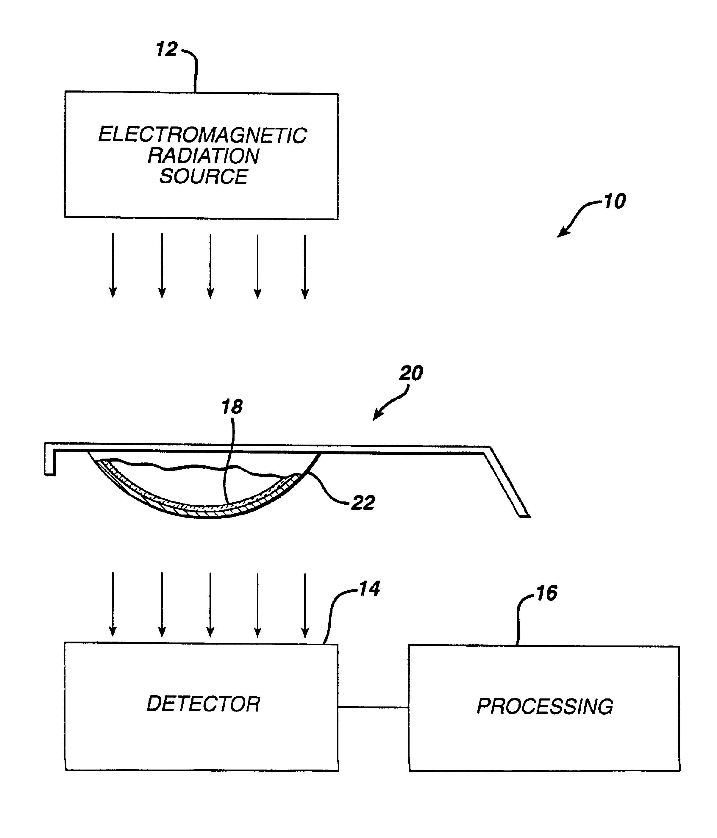
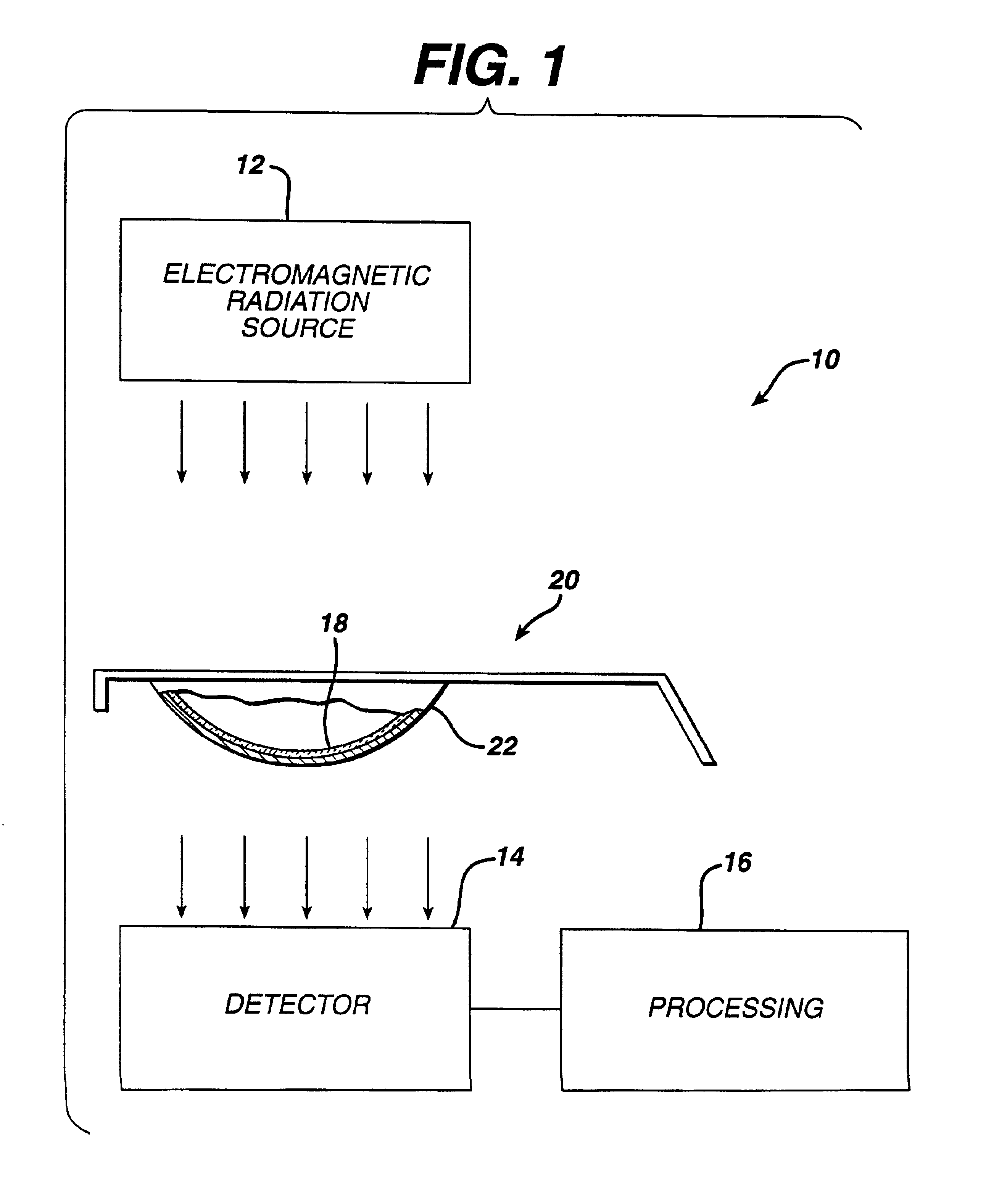
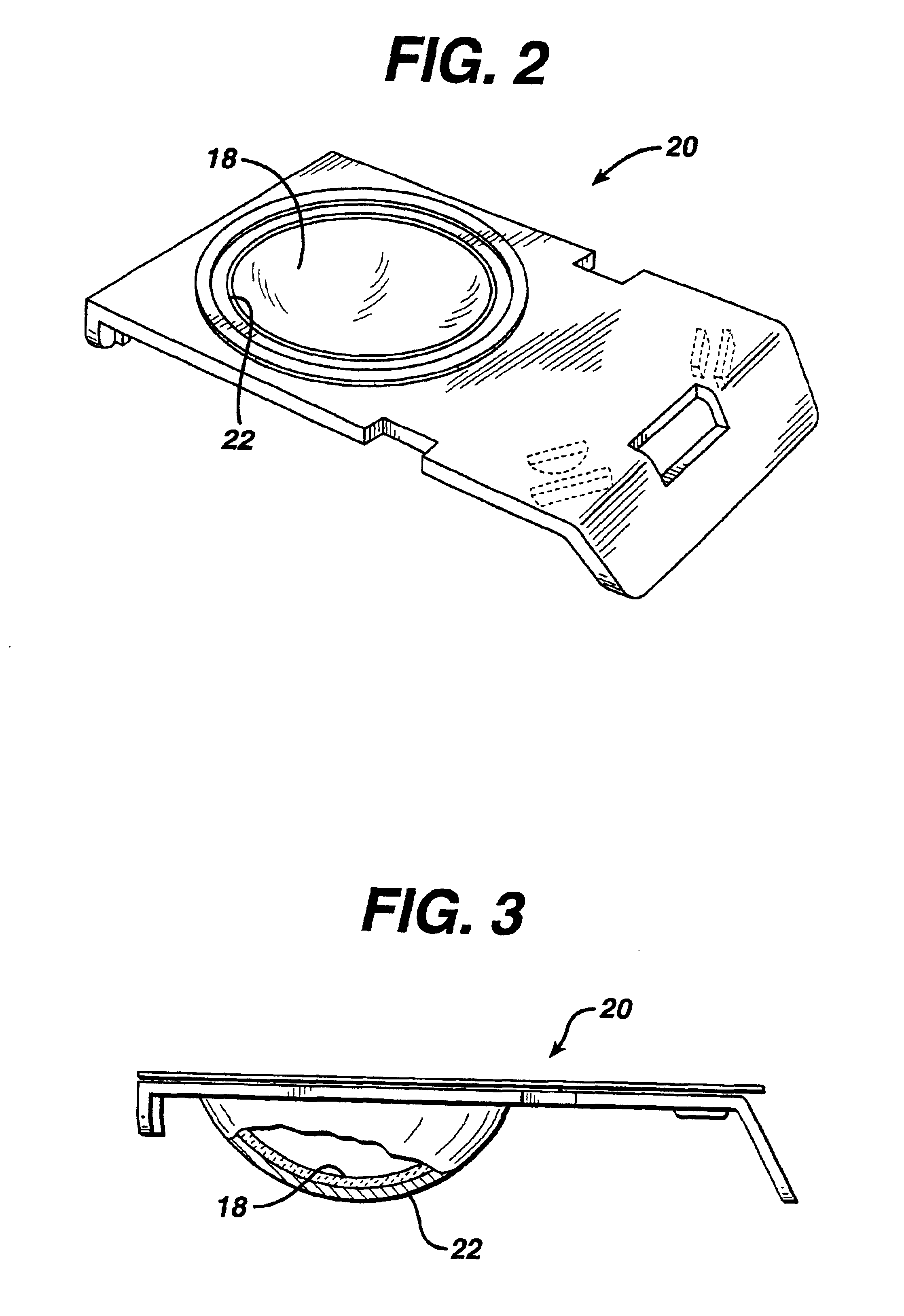
Referring now to the several figures of the drawings, there is depicted a missing lens detection system generally characterized by the reference numeral 10. Referring to FIG. 1, the detection system 10 comprises an electromagnetic radiation source 12 and a detector 14. The source 12 can be a broad-band source which produces ultraviolet light, visible light, and infrared light. For example, a visible light source will produce a portion of the electromagnetic radiation in the ultraviolet band. Alternatively, the source 12 can generate electromagnetic radiation in a narrow band, e.g., ultraviolet (a wavelength or range of wavelengths within about 190 to 400 nanometers). In yet another embodiment, the source 12 can produce electromagnetic radiation in a selected group of ranges such as the ultraviolet and visible band. Similarly, the detector 14 may be responsive to wavelengths of radiation in a particular range, or it may be responsive to broad bands and / or used in combination with a f...


PUM


Abstract

A system for determining the presence and optionally the position of an ophthalmic product such as a contact lens in a container is provided.

Description

FIELD OF THE INVENTIONThe present invention relates generally to systems for detecting the presence and optionally the position of a product within a container or package, and more particularly, to an apparatus and method for verifying the presence in the container of an ophthalmic product such as a contact lens.BACKGROUND OF THE INVENTIONAutomated systems are used for producing ophthalmic lenses as disclosed in U.S. Pat. No. 5,080,839. These systems have achieved a very high degree of automation and enable lenses to be molded, removed from the molds, further processed and subsequently packaged, all without any direct human involvement. Even with highly automated systems, however, it has been necessary for each package to be checked visually by personnel to verify that the package contained a lens. These arrangements have increased manpower requirements and the associated labor costs. Automated loading of lenses without verifying an actual transfer of a contact lens into a package c...

Claims


Application Information

Patent Timeline
IPC IPC(8): B65B25/00B65B57/10B65B57/00G01N21/88G01N21/95
CPCB65B25/008G01N21/9508B65B57/10B29D11/00951
Inventor ROSS, III, DENWOOD F.NEWTON, TIMOTHY P.
Owner JOHNSON & JOHNSON VISION CARE INC
Why Eureka
Try Eureka