Microwave transistor structure having step drain region

a transistor and micro-wave technology, applied in the direction of basic electric elements, electrical equipment, semiconductor devices, etc., can solve the problem of limiting the thc performance of the present available structure, and achieve the effect of improving the performance of high-voltage ldmos devices

Inactive Publication Date: 2005-01-04
QORVO US INC
View PDF1 Cites 20 Cited by
  • Summary
  • Abstract
  • Description
  • Claims
  • Application Information

AI Technical Summary

Problems solved by technology

As the applications for wireless communications move up in the frequency spectrum, parasitic resistances, capacitances and inductances limit thc performance of present available structures.

Method used


Image

  • Microwave transistor structure having step drain region
  • Microwave transistor structure having step drain region
  • Microwave transistor structure having step drain region

Examples


Embodiment Construction

.

Reference will now be made in detail to the preferred embodiments of the invention, examples of which are illustrated in the accompanying drawings. While the invention will be described in conjunction with the preferred embodiments, it will be understood that they are not intended to limit the invention to these embodiments. On the contrary, the invention is intended to cover alternatives, modifications and equivalents that may be included within the spirit and scope of the invention as defined by the appended claims. Furthermore, in the following detailed description of the present invention, numerous specific details are set forth in order to provide a thorough understanding of the present invention. However, it will be obvious to one of ordinary skill in the art that the present invention may be practiced without these specific details. In other instances, well known methods, procedures, components, and circuits have not been described in detail as not to unnecessarily obscure a...


PUM


Abstract

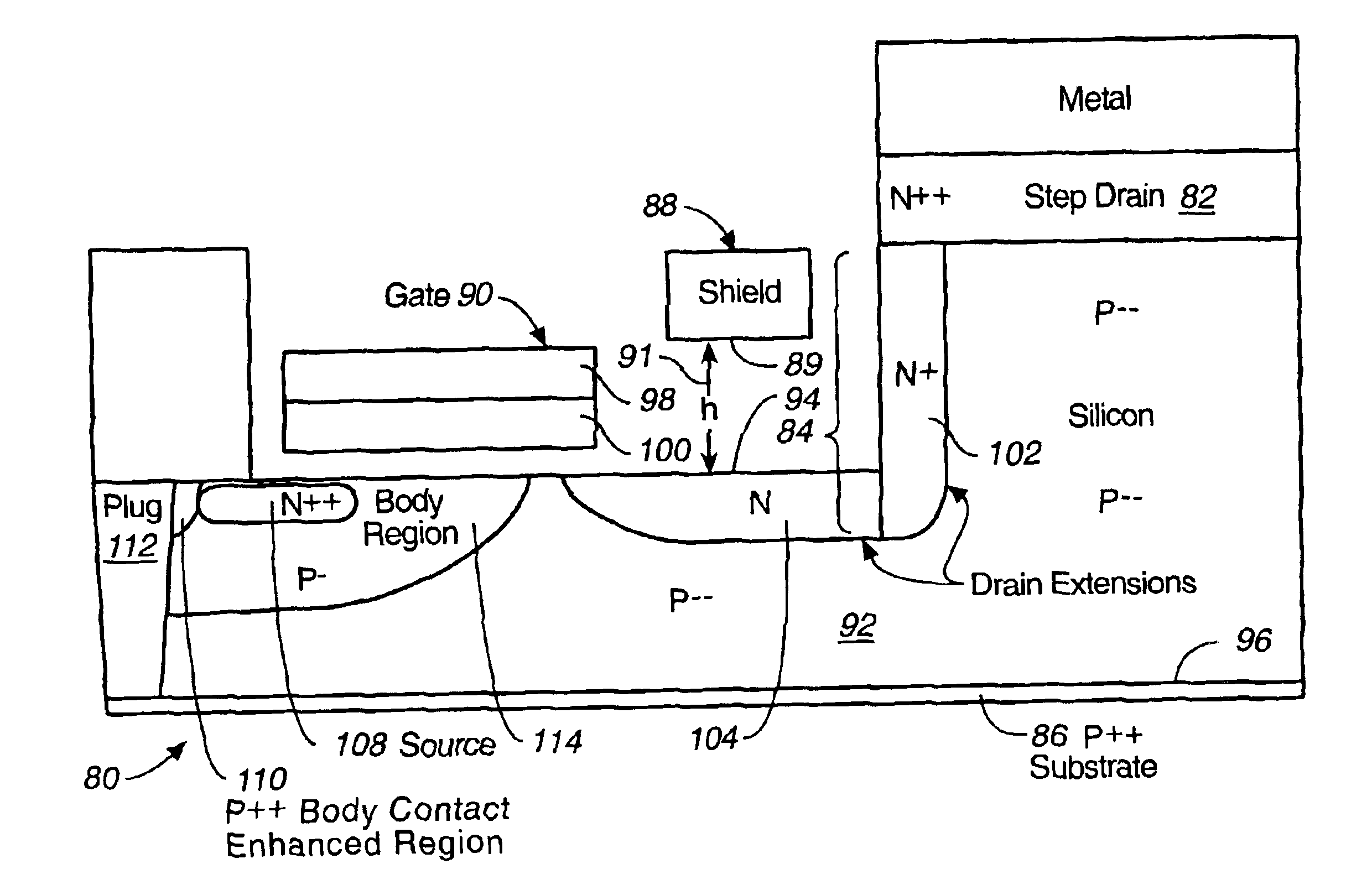
A microwave transistor structure having a step drain region comprising: (A) a substrate having a top surface; (B) a silicon semiconductor material of a first conductivity type, having a first dopant concentration and a top surface; (C) a conductive gate overlying and insulated from the top surface of the silicon semiconductor material; (D) at least one horizontal drain extension region of a second conductivity type and having a horizontal drain extension dopant concentration; (E) a step drain region formed in the silicon semiconductor material, and contacting the horizontal drain extension region; (F) a body region of the first conductivity type and having a body region dopant concentration; (G) a source region of the second conductivity type and having a source region dopant concentration; (H) a shield plate region formed on the top surface of the silicon semiconductor material over a portion of the horizontal drain extension region, the shield plate being adjacent and parallel to the horizontal drain extension region; the shield plate being adjacent and parallel to the conductive gate region; and (I) a conductive plug region.

Description

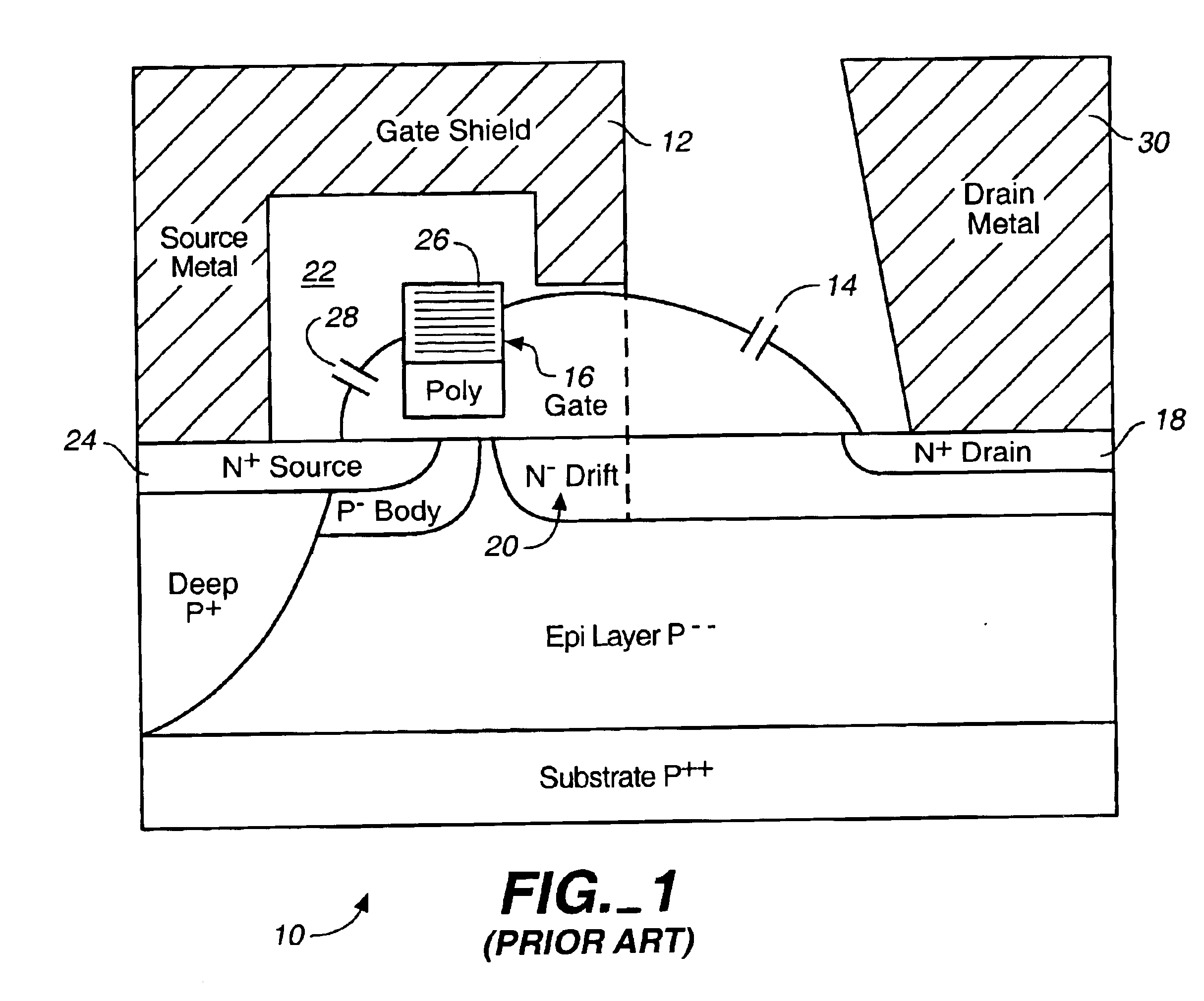
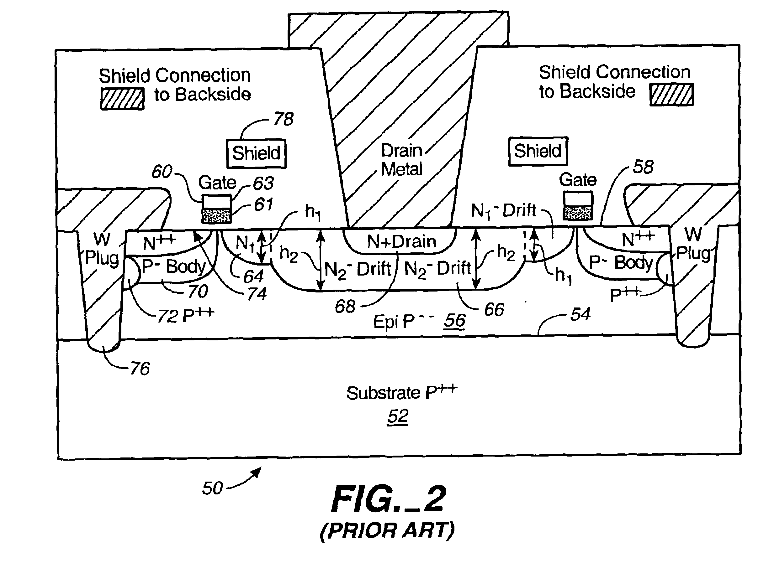
BACKGROUND OF THE INVENTION1. Field of the InventionThe present invention is in the field of microwave field effect transistors, and more specifically, is in the field of a new Silicon power LDMOS structure optimized for operation above 3 GHz, for use in wireless communication applications.2. Discussion of the Prior ArtThe prior art power MOS devices have been widely used lately in wireless communication RF amplifiers for their better linearity, thermal stability and ruggedness as compared to bipolar devices. As the applications for wireless communications move up in the frequency spectrum, parasitic resistances, capacitances and inductances limit thc performance of present available structures. More specifically, in the available prior art LDMOS structures that are designed for the highest operational bands of wireless communications the effect of parasitic drain-to-source (Cds) and drain-to-gate (Cdg) capacitances is too big and has to be reduced to achieve the best performance.Th...

Claims


Application Information

Patent Timeline
Patent Type & Authority Patents(United States)
IPC IPC(8): H01L29/66H01L29/76H01L29/06H01L29/08H01L29/417H01L29/78
CPCH01L29/7835H01L29/41766H01L29/0657H01L29/0847H01L29/4175H01L29/402
Inventor D'ANNA, PABLOJOHNSON, JOSEPH H.
Owner QORVO US INC
Why Eureka
Try Eureka