Component with a label

a technology of components and labels, applied in the field of components, can solve the problems of no labels at all, difficult to read labels,

Inactive Publication Date: 2005-01-04
SNAPTRACK
View PDF3 Cites 27 Cited by
  • Summary
  • Abstract
  • Description
  • Claims
  • Application Information

AI Technical Summary

Benefits of technology

However, other materials can be selected for the contrast layer, for example lacquer layers and, in particular, colored lacquer layers, especially black lacquer layers. In general, it is advantageous when the contrast layer exhibits a different color compared to the metal layer or, in particular, is a black layer.

Problems solved by technology

Only labels that are difficult to read or no labels at all can be generated with laser labeling on miniaturized components that comprise a metallic layer on the surfaces available for a label since adequate contrast cannot be achieved there by erosion of material.

Method used


Image

  • Component with a label
  • Component with a label

Examples


Embodiment Construction

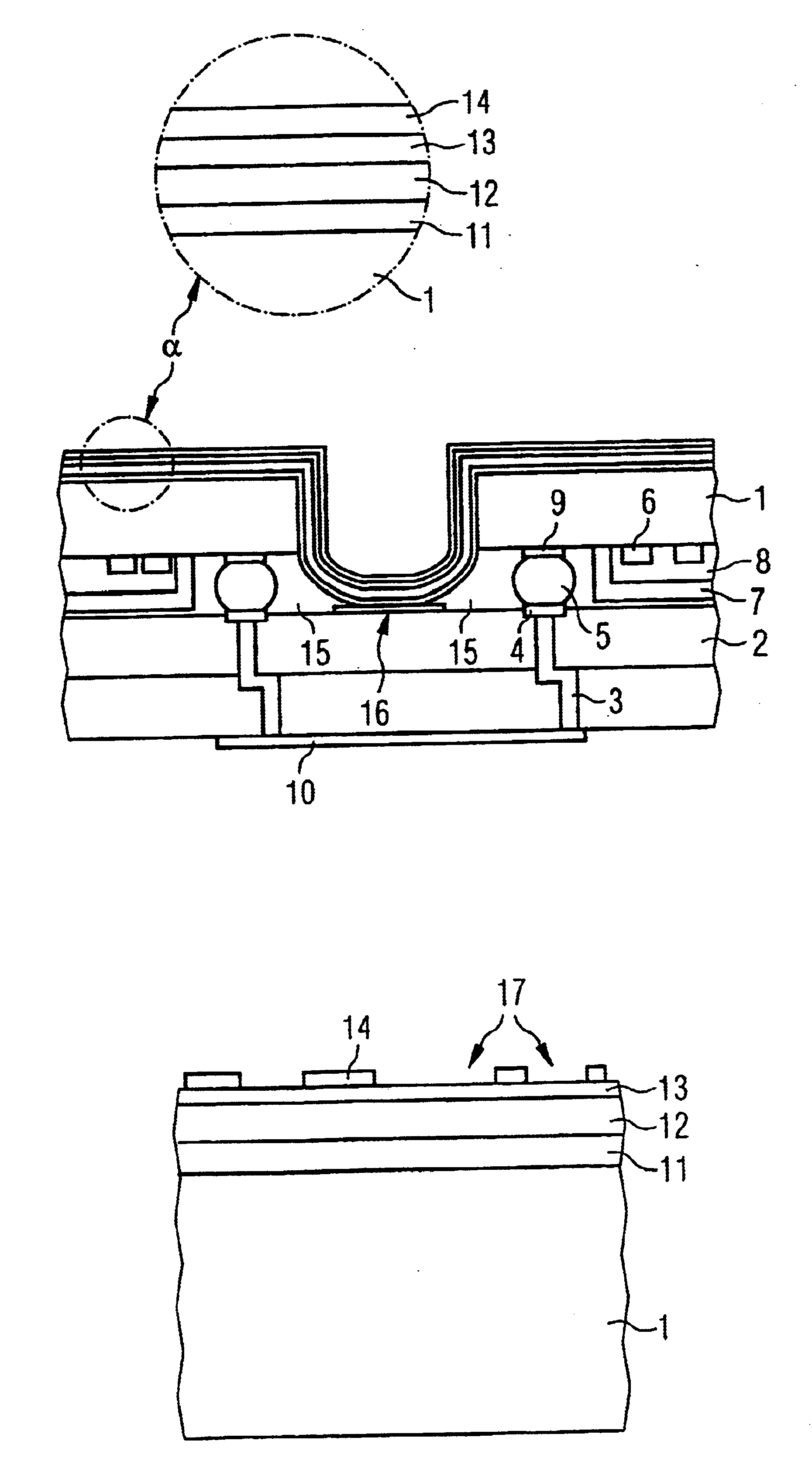
A preferred application of the invention is for surface-wave components, particularly surface-wave filters that are applied on base panels or substrates 2 in flip-chip technology. The piezoelectric component substrate or chip 1 that carries the active component structure 6 is thereby connected face-down to the panel 2 via suitable solder connections 5, particularly via bumps, so that the component structures are arranged protected between component substrate 1 and panel 2 at a clear distance from the latter. Preferably, a plurality of components are thereby applied on one panel and only separated after the completion of all cover layers. As shown, the active component structures 6 can also be additionally covered with a cover cap 7 that is generated directly on the surface of the component substrate 1 (chip) in an integrated process called PROTEC by the assignee. This leaves a clear cavity 8 over the component structures 6 that mechanically protects it during the process.

The bumps 5...


PUM

PropertyMeasurementUnit
thickaaaaaaaaaa
optical contrastaaaaaaaaaa
colorsaaaaaaaaaa

Abstract

For labeling a component provided with a metallic cover layer, it is proposed that at least one additional contrast layer is arranged over the cover layer. The contrast layer produces an optical contrast with the metallic cover layer and is capable of being eroded by a laser for producing a label.

Description

BACKGROUND OF THE INVENTIONThe invention is directed to a component, particularly to a miniaturized, passive component.For identifying electrical, electronic and, in particular, passive components, these are usually provided with a label. This can provide information about the manufacturer, the type or the specifications of the component and, potentially, the serial number or article designation. Larger components that comprise adequately large surfaces for the acceptance of a label can, for example, be printed with silkscreening in a simple way. Given smaller components having dimensions of, for example, below 1 mm, enough printable surface for producing a label is not available. Alternatively, these components can be labeled with a laser beam that still enables even the minutest font sizes to be produced.Only labels that are difficult to read or no labels at all can be generated with laser labeling on miniaturized components that comprise a metallic layer on the surfaces available...

Claims


Application Information

Patent Timeline
Patent Type & Authority Patents(United States)
IPC IPC(8): G09F3/00G09F7/16G09F7/00H01L23/02H01L23/544H01L23/10H01L23/552H01L41/09H01L41/22H01L41/29H01L41/313H03H9/25
CPCC23C28/021C23C28/028G09F3/00G09F7/165H01L23/10H01L23/544H01L23/552C23C28/023B41M5/24H01L2223/54473H01L2224/16H01L2924/0102H01L2924/01078H01L2924/01079H01L2924/16235H01L2924/3025H01L2924/01068H01L2224/05573H01L2224/05568H01L2924/00014H01L2224/16227H01L2224/05599
Inventor STELZL, ALOISKRUGER, HANSCHRISTI, ERNST
Owner SNAPTRACK
Why Eureka
Try Eureka