Power feeding apparatus for discharge lamp

a technology of power feeding apparatus and discharge lamp, which is applied in the direction of electric variable regulation, process and machine control, instruments, etc., can solve the problems of increasing the cost of optical apparatus, unable to avoid cost rise, and unable to obtain the practical light intensity of discharge lamp waiting time, so as to prevent shortening the life of discharge lamp

Inactive Publication Date: 2005-01-04
USHIO DENKI KK
View PDF8 Cites 10 Cited by
  • Summary
  • Abstract
  • Description
  • Claims
  • Application Information

AI Technical Summary

Benefits of technology

It is an object of the present invention to prevent from shorteni

Problems solved by technology

Since the discharge lamp voltage is low such as about 10 V just after the discharge form changes from the glow discharge to the arc discharge, excessive large current is required to supply rated apparent power at that time.
Therefore growth in size or by weight, cost rise of the optical apparatus cannot be avoided.
Thus, the waiting time to obtain the practical light intensity from the discharge lamp becomes longer.
Therefore, due to the physical restriction such as cost, size, weight of the optical apparatus and the practical restriction such as the waiting time for which the optical apparatus can be used, the setting range of the current limit value (IL0) is limited.
Whatever kind of a power feeding apparatus is used, generally, it is difficult to supply power to a high voltage load, and it is easy to supply power to a low voltage load.
However, in fact, such a switching circuit can control the capability only at discrete t

Method used


Image

  • Power feeding apparatus for discharge lamp
  • Power feeding apparatus for discharge lamp
  • Power feeding apparatus for discharge lamp

Examples


third embodiment

A third embodiment is described below.

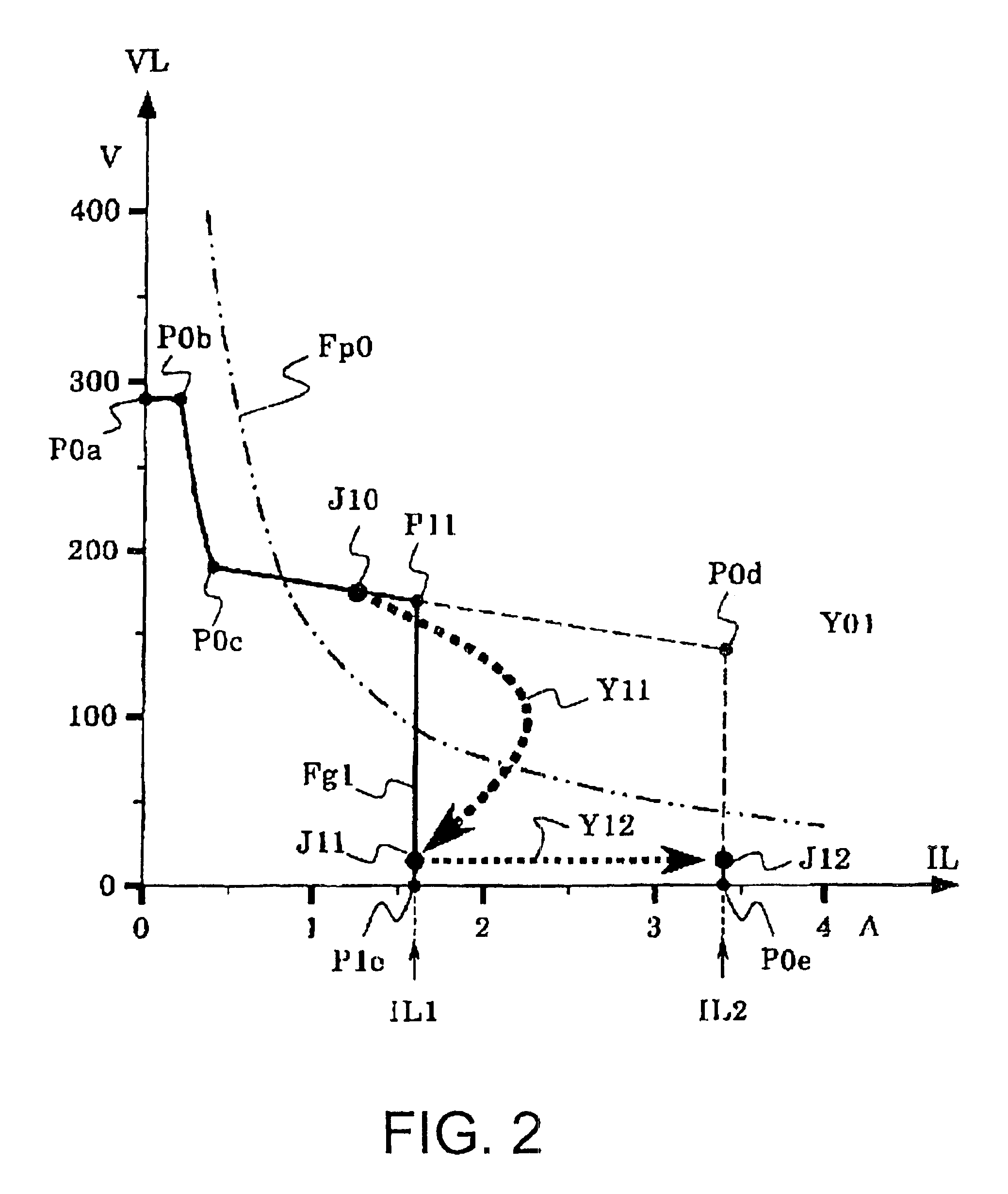
In the above-described examples, part of the characteristic line, such as a portion between the point (P11) and the point (P1e) or the point (P0d) and (P0e) shown in FIG. 2 or a portion between the point (P11) and (P12) or the point (P12) and the point (P0e) shown in FIG. 8 is parallel to the VL axis, that is, the current limit value does not depend on the discharge lamp voltage.

In case that part of the characteristic line is not parallel to the VL axis, that is, the current limit value depends on the discharge lamp voltage, the present invention may be effectively applied.

In case hat for Example, as shown in FIG. 11, the output current / voltage characteristic before the discharge state changes to the arc discharge is shown as a characteristic line (Fg31) connecting between a point (P30) and a point (P32) and after the discharge status changes to the arc discharge, even though the output current / voltage characteristic is shown as a characteristic...


PUM


Abstract

In a power feeding apparatus, current flowing through the discharge lamp is controlled not to exceed a current limit value. Until the discharge status changes to the arc discharge, the current limit value is a first current limit value, and after that, the current limit value changes to the second current limit value. The first current limit value is 70% of the second current limit value or less, and further, for 0.2 ms or greater, the first current limit value is maintained after the discharge status changes to the arc discharge.

Description

TECHNICAL FIELD OF THE INVENTIONThis invention relates to a power feeding apparatus for a discharge lamp used as a light source of an optical apparatus such as a projector etc, which turns on a high-intensity discharge lamp (HID lamp) such as a high-pressure mercury discharge lamp or metal halide lamp.DESCRIPTION OF RELATED ARTA high-intensity discharge lamp is used, in combination with a power feeding apparatus for turning on the high-intensity discharge lamp, for an optical apparatus such as a liquid crystal projector or DLP™ (Texas Instruments Incorporated) projector.There are two discharge lamp driving methods, that is, a DC driving method in which there is no change of polarity relationship that one of the two poles is cathode and the other is an anode, and an AC driving method in which polarity relationship changes alternatively. In the AC driving method, it is possible to drive the discharge lamp in a broad driving frequency band (speed of polarity change) such as from severa...

Claims


Application Information

Patent Timeline
IPC IPC(8): H05B41/292H05B41/38H05B41/28H05B41/24H05B41/282
CPCH05B41/2928H05B41/388Y02B20/208Y02B20/00
Inventor OKAMOTO, MASASHIFUKUDA, MINORUTAKEKIYO, ATSUSHI
Owner USHIO DENKI KK
Why Eureka
Try Eureka