
One-chip microcomputer with analog-to-digital converter

Inactive Publication Date: 2005-01-04
RENESAS ELECTRONICS CORP +1
View PDF15 Cites 65 Cited by
  • Summary
  • Abstract
  • Description
  • Claims
  • Application Information

AI Technical Summary

Benefits of technology

An object of the present invention is to provide, with due consideration to the drawbacks of the conventional one-chip microcomputer, a one-chip microcomputer with an analog-to-digital converter in which an analog input signal received at an analog input terminal or each of a plurality of analog input terminals is correctly and immediately recognized in a low electric power consumption.
Therefore, in cases where a user does not desire to receive digital data obtained from analog input signals received at an analog input terminal, the analog-to-digital conversion start request generating circuit corresponding to the analog input terminal can be inhibited from generating an analog-to-digital conversion start request signal. Accordingly, because the analog-to-digital converter is not operated for the analog input signals received at the analog input terminal, the electric power consumed in the one-chip microcomputer can be further reduced.

Problems solved by technology

As a result, it is inconvenient to use the key matrix type input circuit for the conventional one-chip microcomputer.
Therefore, a problem has arisen that an electric power is consumed to always or intermittently set the A / D converter 8 to the operation state.
Therefore, another problem has arisen that an electric power is consumed to always operate the CPU and the clock.
In this case, it is difficult for the conventional one-chip microcomputer 1 to immediately recognize an analog input terminal 7 from which an analog input signal is sent.
Therefore, in cases where a plurality of analog input terminals 7 are arranged in the conventional one-chip microcomputer 1, a problem has arisen that it takes a lot of time to recognize an analog signal received at each analog input terminal.

Method used


Image

  • One-chip microcomputer with analog-to-digital converter
  • One-chip microcomputer with analog-to-digital converter
  • One-chip microcomputer with analog-to-digital converter

Examples


embodiment 1

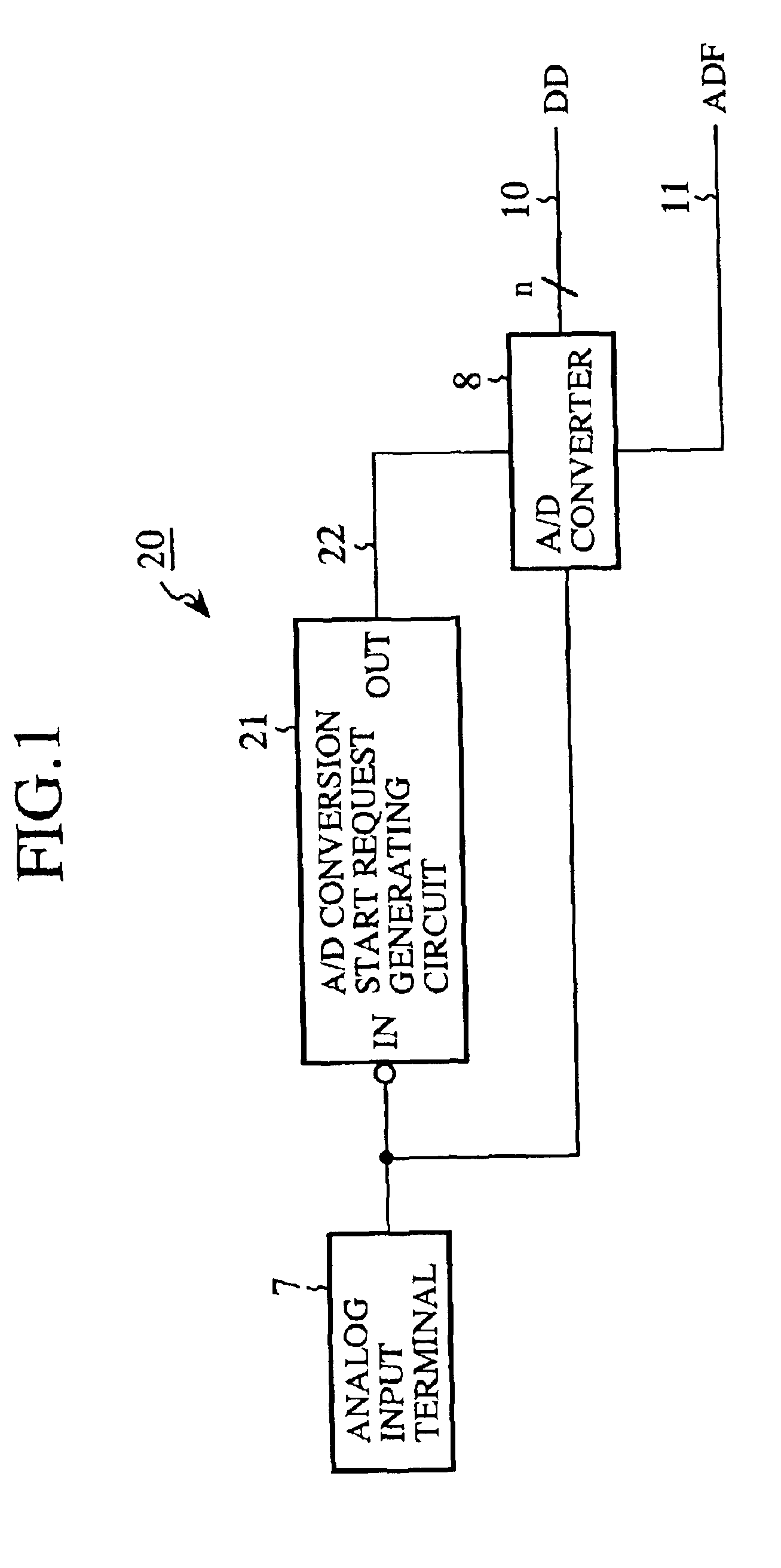
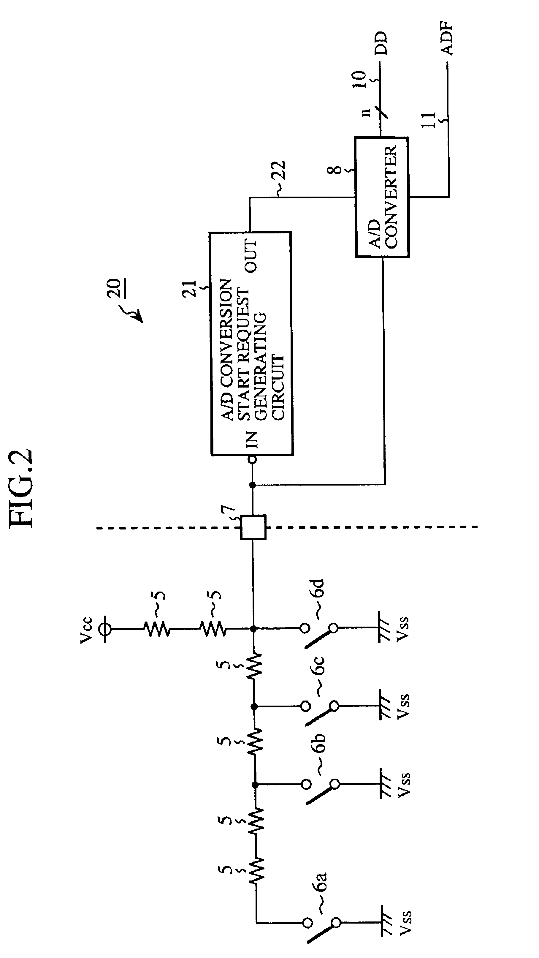
FIG. 1 is a circuit view showing a one-chip microcomputer with an A / D converter connected to an analog input terminal according to a first embodiment of the present invention.

In FIG. 1, 20 indicates a one-chip microcomputer. 7 indicates an analog input terminal for receiving an analog input signal set to a level lower than a high (H) level. 21 indicates an A / D conversion start request generating circuit for judging whether or not the analog input signal received at the analog input terminal 7 is a significant signal having a significant level, and generating an A / D conversion start request signal in response to the analog input signal judged to be a significant signal. 22 indicates a signal line through which the A / D conversion start request signal generated in the A / D conversion start request generating circuit 21 is transmitted. 8 indicates an A / D converter for converting the analog input signal received at the analog input terminal 7 into digital data DD in response to the A / D co...

embodiment 2

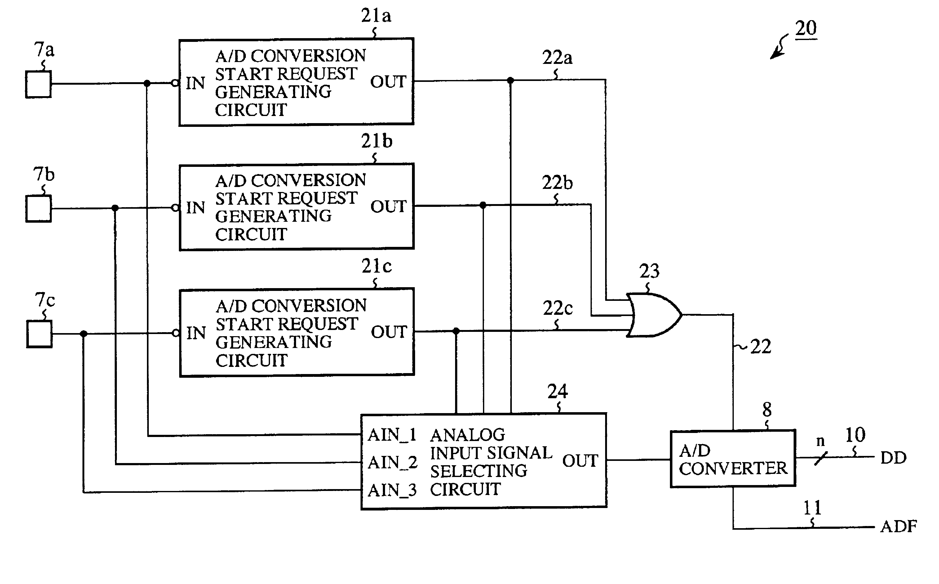
FIG. 3 is a circuit view showing a one-chip microcomputer with an A / D converter connected to a plurality of analog input terminals according to a second embodiment of the present invention. The constituent elements, which are the same as those shown in FIG. 1, are indicated by the same reference numerals as those of the constituent elements shown in FIG. 1, and additional description of those constituent elements is omitted.

In FIG. 3, 7a to 7c indicate a plurality of analog input terminals for respectively receiving an analog input signal set to a level lower than the H level from the external switching circuit composed of the resistors 5 and the switched 6a to 6d.

21a to 21c indicate a plurality of A / D conversion start request generating circuits, connected to the analog input terminals 7a to 7c respectively, for respectively judging whether or not an analog input signal received at the corresponding analog input terminal 7a, 7b or 7c is a significant signal having a significant le...

embodiment 3

In the second embodiment, a plurality of analog input signals having significant levels are received one after another at the analog input terminals. In contrast, in a third embodiment, a plurality of analog input signals having significant levels are simultaneously received at a plurality of analog input terminals respectively.

FIG. 4 is a circuit view showing a one-chip microcomputer with an A / D converter connected to a plurality of analog input terminals according to a third embodiment of the present invention. The constituent elements, which are the same as those shown in FIG. 3, are indicated by the same reference numerals as those of the constituent elements shown in FIG. 3, and additional description of those constituent elements is omitted.

In FIG. 4, 21d indicates an A / D conversion start request generating circuit of a top priority for judging whether or not an analog input signal received at the analog input terminal 7a is a significant signal having a significant level, gen...


PUM


Abstract

An input circuit of a one-chip microcomputer is connected to an external switching circuit. When an analog input signal of a significant level generated in the external switching circuit is received at an analog input terminal of the input circuit, an A / D conversion start request signal is generated in an A / D conversion start request generating circuit and is sent to an A / D converter. The operation of the A / D converter is started in response to the A / D conversion start request signal, the analog input signal received at the analog input terminal is converted into digital data, and an A / D conversion finish signal is sent from the A / D converter to a CPU of the one-chip microcomputer. The operation of the CPU is started in response to the A / D conversion finish signal, and the digital data is readout to the CPU. Therefore, the A / D converter, the CPU or a clock is not operated to wait for an analog input signal generated in the external switching circuit, but the A / D converter is operated for the A / D conversion, and the CPU is operated to read out the digital data. Accordingly, an electric power consumed in the A / D converter, the CPU and the clock can be reduced.

Description

BACKGROUND OF THE INVENTION1. Field of the InventionThe present invention relates to a one-chip microcomputer with an analog-to-digital converter in which a large number of analog signals generated one after another in an external switching circuit are received at a small number of terminals and are recognized.2. Description of Related ArtIn cases where a large number of analog signals are input one after another to a plurality of input terminals of a one-chip microcomputer, a key matrix type circuit or an analog-to-digital (A / D) converter is used as an input circuit of the one-chip microcomputer. In case of the key matrix type input circuit, in cases where the number of input terminals of the one-chip microcomputer is equal to or higher than two and is the same as the number of output terminals of the one-chip microcomputer, a large number of analog signals input one after another to the one-chip microcomputer can be most efficiently recognized.FIG. 9 is a circuit view showing a co...

Claims


Application Information

Patent Timeline
IPC IPC(8): H03M1/00H03M1/12G06F3/05G06F15/78
CPCH03M1/002H03M1/1225G06F15/78
Inventor UDA, NOBUYA
Owner RENESAS ELECTRONICS CORP
Learn More