
Average current mode controlled energy storage in a defibrillator

a defibrillator and current mode technology, applied in the field of medical devices, can solve the problems of particularly life-threatening ventricular fibrillation, and cannot provide the high-energy, high-voltage electric pulse required for defibrillation therapy,

Inactive Publication Date: 2005-01-04
PHYSIO CONTROL INC
View PDF44 Cites 20 Cited by
  • Summary
  • Abstract
  • Description
  • Claims
  • Application Information

AI Technical Summary

Benefits of technology

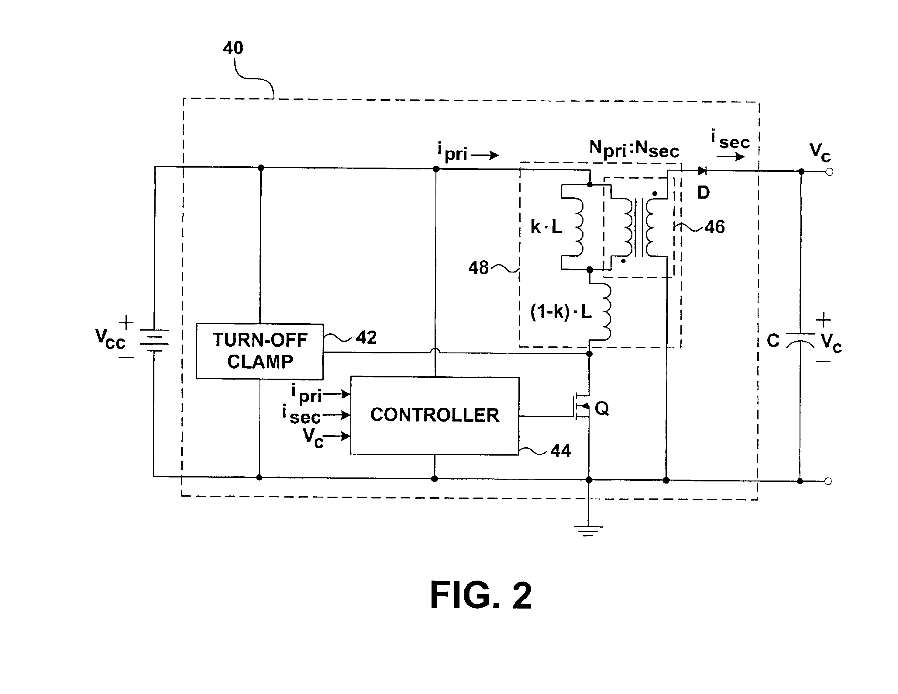
The invention relates to techniques for charging an energy storage device, such as the high-voltage energy storage capacitors of an external defibrillation device, using average current mode control techniques. The time needed to charge a capacitor to a desired voltage is a function of the current flowing to the capacitor. By controlling the average current, the charge time and the voltage across the capacitor can be more effectively controlled.
Average current mode control represents a highly accurate technique for controlling current in a transformer, and consequently represents a highly accurate technique for storing energy in a storage element such as a capacitor in a short time. In devices such as a defibrillator, rapid and accurate energy storage are especially advantageous. The technique may be extended to a wide range of current levels, charge times and voltage levels.
Average current mode control represents an accurate and versatile technique for storing energy in a storage element. By controlling average current, it is possible to control, for example, the time needed to charge a capacitor to a desired voltage level.
In a further embodiment, the invention presents a medical device comprising a difference circuit that generates an error signal as a function of the difference between a reference current and an average current in a transformer that transfers energy to an energy storage device. The device further includes a modulator that modulates the duty cycle of a control signal as a function of the error signal and a switch that regulates the supply of energy to a primary coil of the transformer according to the control signal. The control signal may have a constant period, which advantageously allows for management of the noise spectrum due to the control signal.

Problems solved by technology

Ventricular fibrillation is particularly life threatening because activity within the ventricles of the heart is so uncoordinated that virtually no pumping of blood takes place.
A defibrillator such as a portable defibrillator typically includes a battery, which by itself is not capable of providing the high energy, high-voltage electric pulses required for defibrillation therapy.

Method used


Image

  • Average current mode controlled energy storage in a defibrillator
  • Average current mode controlled energy storage in a defibrillator
  • Average current mode controlled energy storage in a defibrillator

Examples


Embodiment Construction

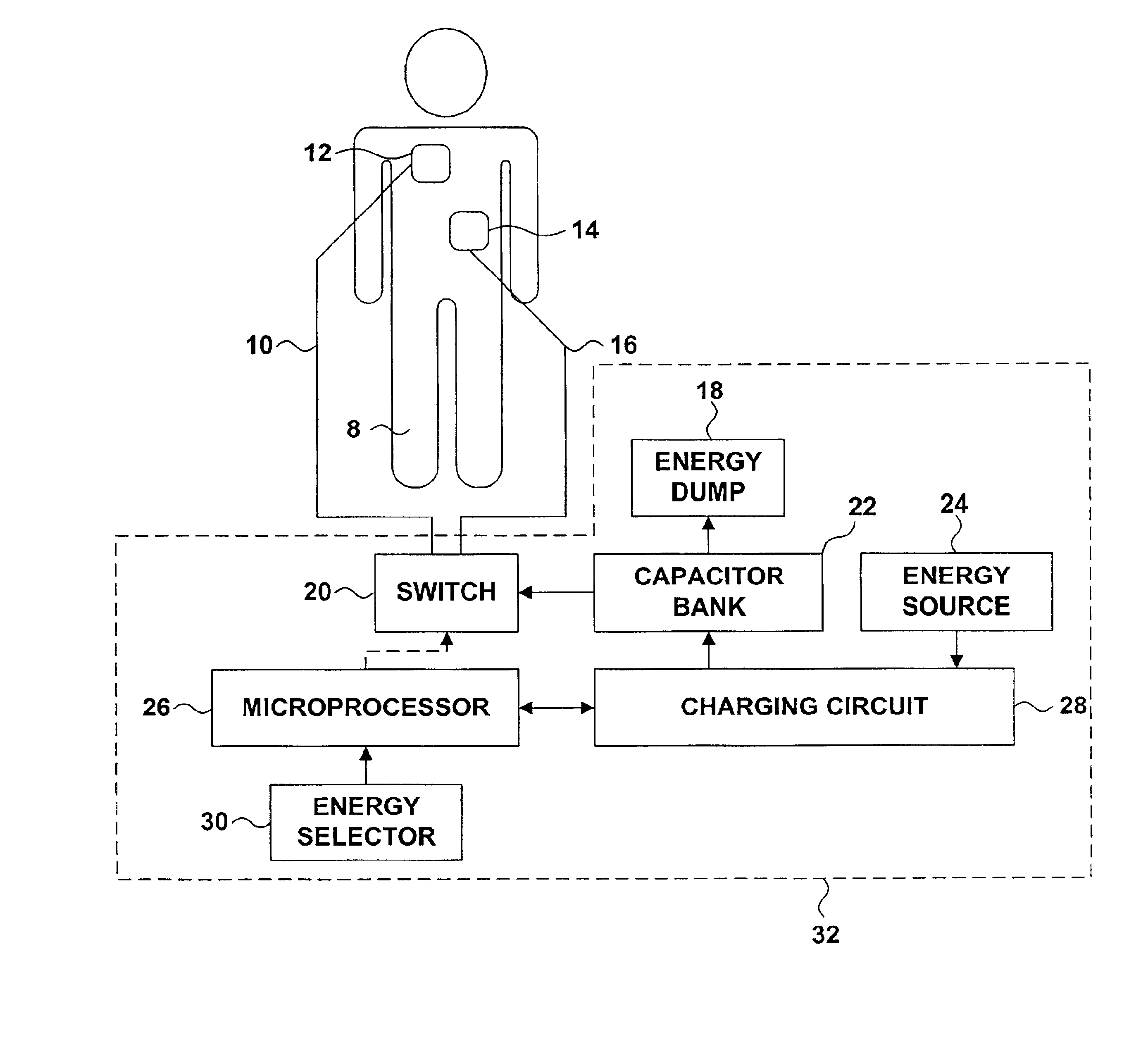
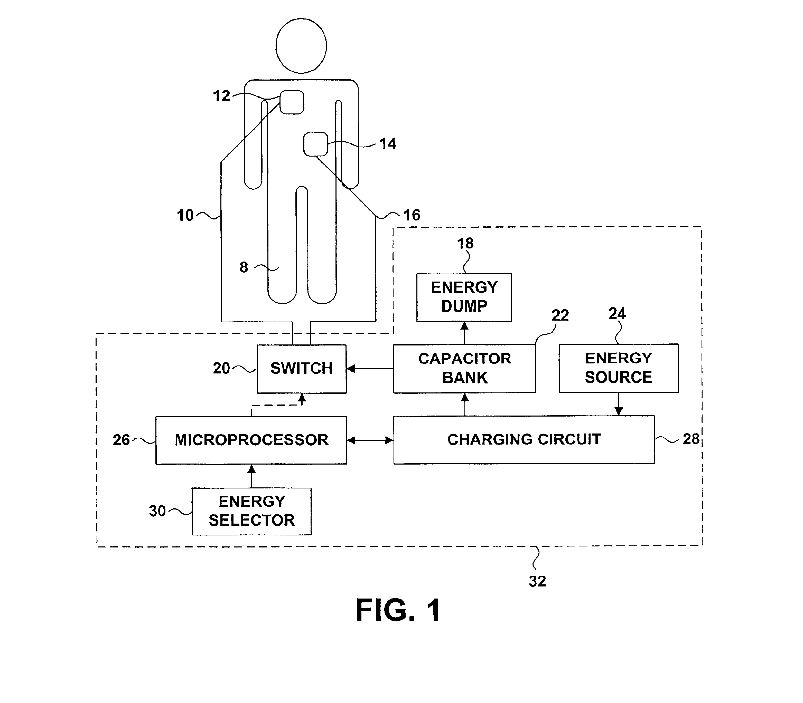
FIG. 1 is a block diagram illustrating components of a defibrillator 32 formed in accordance with the present invention. Defibrillator 32 administers therapy to patient 8 via electrodes 12 and 14, which may be hand-held electrode paddles or adhesive electrode pads placed on the skin of patient 8. The body of patient 8 provides an electrical path between electrodes 12 and 14.

Patient electrodes 12 and 14 are coupled to switch 20 via conductors 10 and 16. Switch 20 couples patient electrodes 12 and 14 to the output of capacitor bank 22. Switch 20 is of conventional design and may be formed, for example, of electrically operated relays. Alternatively, switch 20 may comprise an arrangement of solid-state devices such as silicon-controlled rectifiers or insulated gate bipolar transistors. In each case, switch 20 should be capable of carrying relatively high currents.

Capacitor bank 28 stores the energy to be delivered to patient 8. The amount of energy to be delivered may be specified by a...


PUM


Abstract

Techniques are described for charging an energy storage device, such as the high-voltage energy storage capacitors of an external defibrillation device, using an average current mode control technique. By controlling the average current in a transformer, energy may be stored rapidly and at controlled energy levels.

Description

TECHNICAL FIELDThe invention relates generally to energy storage techniques for medical devices, and more particularly techniques employing switching-mode devices to store energy in an energy storage device associated with a defibrillator.BACKGROUNDMany devices rely on an energy storage device such as a capacitor to store potential energy and supply a voltage to a load. Examples of such devices include photographic flash lamps and flashing warning lights.A defibrillator is another device that stores energy, typically in one or more high-voltage capacitors, and delivers the stored energy to a patient. In particular, a defibrillator delivers energy to a heart that is undergoing fibrillation and has lost its ability to contract. Ventricular fibrillation is particularly life threatening because activity within the ventricles of the heart is so uncoordinated that virtually no pumping of blood takes place. An electrical pulse delivered to a fibrillating heart may repolarize the heart and ...

Claims


Application Information

Patent Timeline
IPC IPC(8): A61N1/39
CPCA61N1/3975A61N1/3981
Inventor WALTMAN, BARRY F.
Owner PHYSIO CONTROL INC
Learn More