Plumbing supply monitoring, modeling and sizing system and method

a technology of sizing system and sizing supply, applied in the field of sizing system, can solve the problems of inability to monitor continuously 24 hours per day, requiring extensive wiring, and difficult to perform and/or install in existing facilities

Inactive Publication Date: 2005-01-04
TEXAS A&M UNIVERSITY
View PDF8 Cites 56 Cited by
  • Summary
  • Abstract
  • Description
  • Claims
  • Application Information

AI Technical Summary

Benefits of technology

The present invention provides a method and system for monitoring a plumbing system using a monitoring system vibrationally coupled to the plumbing system. Particular embodiments of the present invention provide a passive, non-invasive, opaque-to-facility-users, portable, and low-cost system and method for monitoring, modeling and sizing plumbing systems. Such embodiments present considerable advantages over existing techniques for monitoring plumbing systems.

Problems solved by technology

However, this has obvious social drawbacks.
A person could monitor facility use, but in additional to social drawbacks, the person could not monitor continuously for 24 hours per day.
Sensors (magnetic relay or optical relay) could be mounted in some fashion at each fixture, but this would require extensive wiring that is difficult to perform and / or install in existing facilities.
Flow meters could be installed in the supply lines for each of the fixture groups (water closet, urinal, lavatory), but this may be a prohibitively expensive and difficult option.
Access to the piping supply risers is typically very limited, the cost per fixture group would be significant, and such metering would require shutdown of the facility for installation and removal of the flow meters.

Method used


Image

  • Plumbing supply monitoring, modeling and sizing system and method
  • Plumbing supply monitoring, modeling and sizing system and method
  • Plumbing supply monitoring, modeling and sizing system and method

Examples


Embodiment Construction

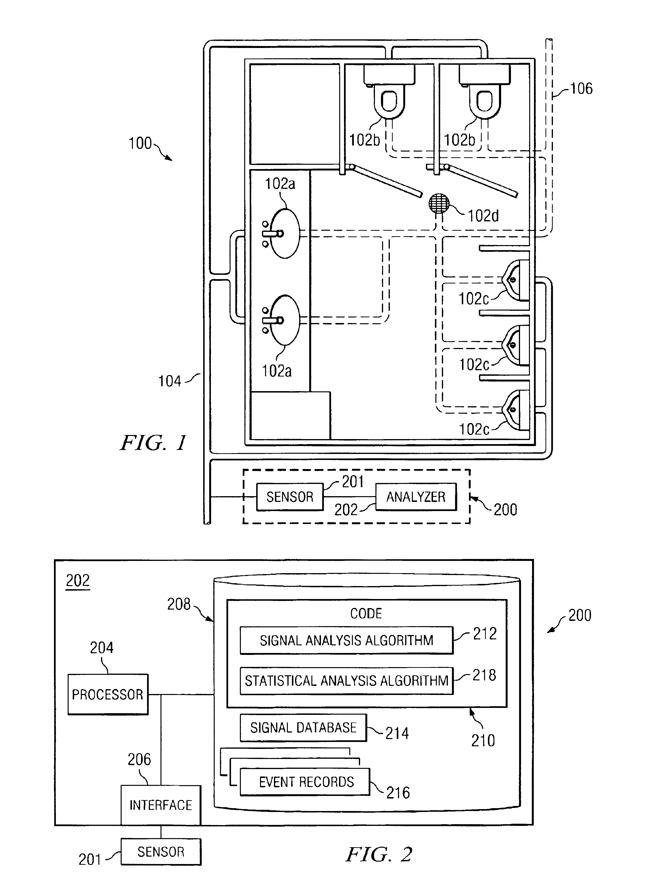
FIG. 1 shows a plumbing system 100 that provides water services to a plurality of fixtures 102 (referring generally to fixtures 102a, 102b, 102c, and 102d). Supply lines 104 provide water or other fluid to fixtures 102, while drain lines 106 remove waste water or fluid from fixtures 102. Monitoring system 200 is vibrationally coupled to plumbing system 100. In general, monitoring system 200 detects vibrations produced by the operation of one or more fixtures 102 and determines that the detected vibration corresponds to the operation of the one or more fixtures 102 that generated the vibration.

Fixtures 102 represent any components of plumbing system 100 that use water from plumbing system 100 or provide waste water to plumbing system 100 for disposal. In the depicted embodiment, fixtures 102 include lavatories 102a, water closets 102b, urinals 102c, and a floor drain 102d. Those components, however, are only examples, and plumbing system 100 may include other fixtures 102, including ...


PUM


Abstract

A system for monitoring a plumbing system having a plurality of fixtures includes a sensor vibrationally coupled to the plumbing system and a processor. The sensor detects a vibration produced by the plumbing system, and generates a signal representative of the vibration. The processor receives the signal, compares the signal to a signal database that associates each of a plurality of stored signals with operation of one or more of the fixtures, and determines that the associated fixture or group of fixtures has been operated based on the comparison. The processor also stores a record of the operation of the associated fixture or group of fixtures.

Description

TECHNICAL FIELD OF THE INVENTIONThis invention relates in general to the field of plumbing systems and, more particularly, to a plumbing supply monitoring, modeling and sizing system and method.BACKGROUND OF THE INVENTIONHaving an accurate determination of the amount of fixture usage in a plumbing system may be useful for a variety of reasons. The level of usage may help to predict the amount of associated resources, such as water supply or paper products, used in conjunction with the fixtures. It may also be used to assess the amount of wear on components of a plumbing system and to determine when components need to be replaced. Such information may also be used to redesign or improve the plumbing system in order for the system to function more effectively. For these reasons and many others, it is useful to have a method for determining the amount of plumbing fixture usage.One method for monitoring restroom plumbing fixture use may include a camera mounted in the restroom. However,...

Claims


Application Information

Patent Timeline
Patent Type & Authority Patents(United States)
IPC IPC(8): G06F19/00E03C1/01
CPCE03C1/01
Inventor WOODS, PAUL K.BRYANT, JOHN A.PARKER, KENNETH B.
Owner TEXAS A&M UNIVERSITY
Why Eureka
Try Eureka