Combination gear hobber, chamfer/debur and shaver apparatus and method

a technology of chamfer/debur and shaver, which is applied in the direction of gear teeth, manufacturing tools, mechanical equipment, etc., can solve the problems of cycle time converting directly into manufacturing costs and thus component prices, each machine has associated costs, and the initial cost is the capital investment required to purchase the machin

Inactive Publication Date: 2005-01-11
MAGNA DRIVETRAIN OF AMERICA
View PDF11 Cites 11 Cited by
  • Summary
  • Abstract
  • Description
  • Claims
  • Application Information

AI Technical Summary

Problems solved by technology

The cycle-time translates directly into manufacturing costs and thus component price.
In addition to cycle-times, each machine has associated costs.
The initial cost is the capital investment required to purchase the machine.
Other costs are incurred throughout the life of the machine.
These on-going costs include maintenance, replacement parts, general running costs (electricity, lubricant, etc.) and the like.
However, certain limitations are inherent in using multiple-thread hobs.
Although not efficient for mass produ

Method used


Image

  • Combination gear hobber, chamfer/debur and shaver apparatus and method
  • Combination gear hobber, chamfer/debur and shaver apparatus and method
  • Combination gear hobber, chamfer/debur and shaver apparatus and method

Examples


Embodiment Construction

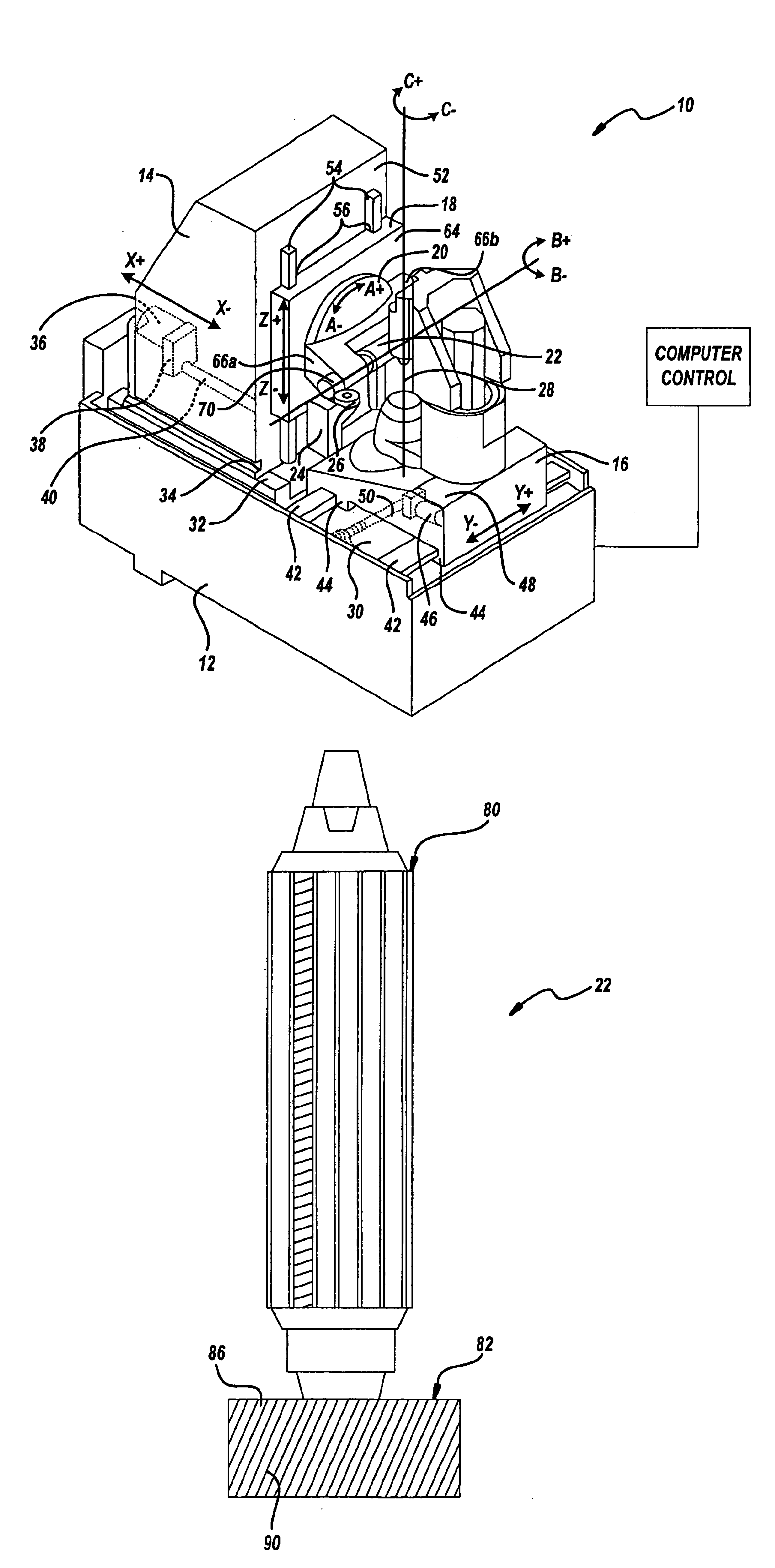
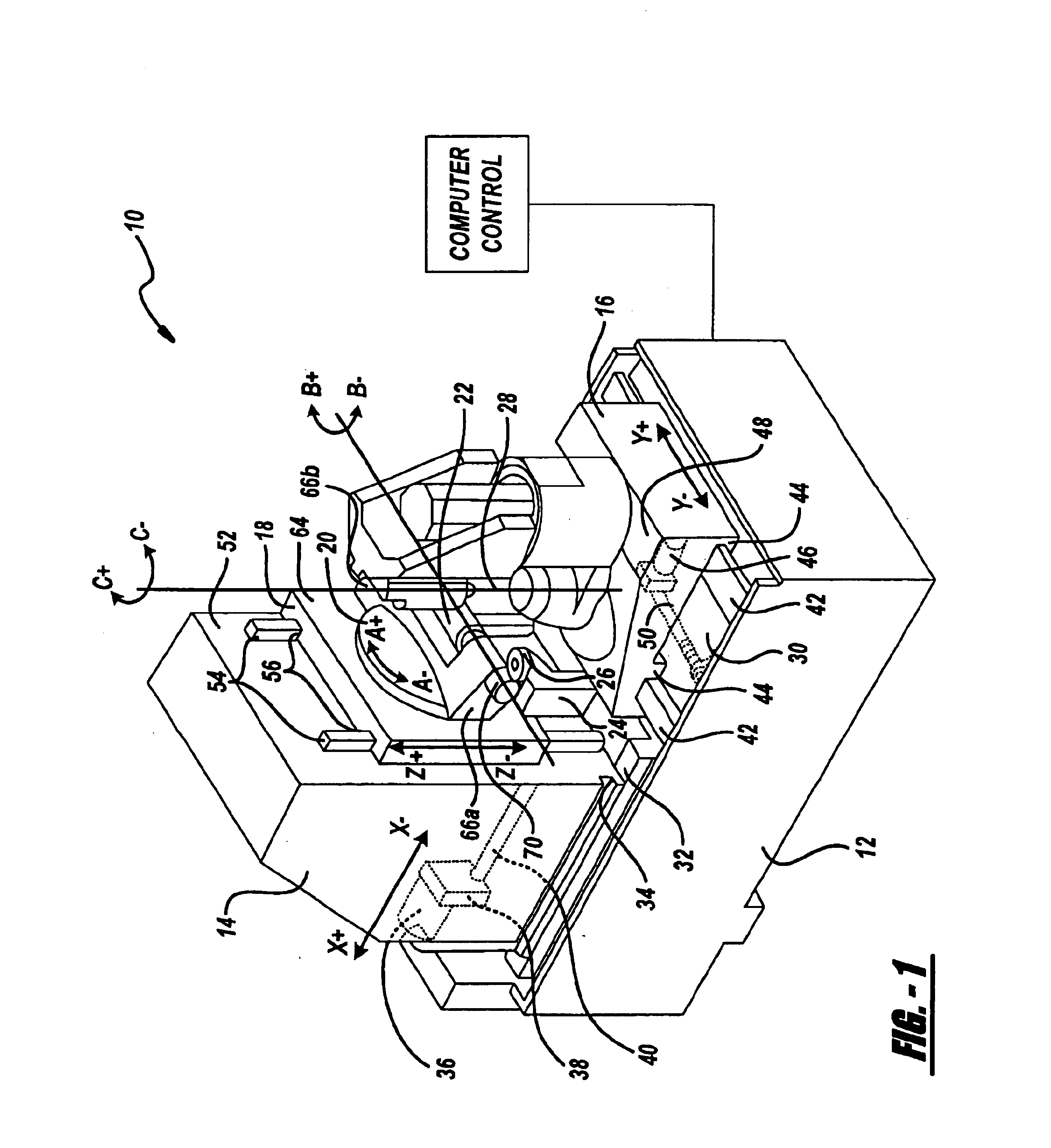
With particular reference to FIG. 1, an exemplary embodiment of a four-process manufacturing apparatus 10 (the apparatus) is shown. The apparatus 10 of the exemplary embodiment is provided for the manufacture of gears. However, it should be noted that the apparatus 10 is preferably variable for manufacture of any one of a number of alternative components. The apparatus 10 and its related components, described in detail below, are preferably CNC controlled by any one of a number of controllers (not shown) commonly known in the art. The controller is programmable for manufacturing a variety of components and / or component designs. It is foreseen that the controller is also programmable to simultaneously control operation of the rectilinear movement of the various stocks described herein.

The apparatus 10 includes a generally rectangular, solid metal base 12 providing a solid support structure for the various apparatus components described herein. First and second stocks 14, 16 are inclu...


PUM

PropertyMeasurementUnit
Timeaaaaaaaaaa
Displacementaaaaaaaaaa

Abstract

An apparatus is provided for manufacturing a gear component. The apparatus includes a plurality of tooling stocks movable relative to a base. The tooling stocks function to retain a component, as well as operably driving a combination hob/shaver tool and a combination chamfer/debut tool. The apparatus reduces the number of machines required to complete the gear component as well as reducing the cycle time for complete component manufacture. In this way, a more efficient manufacturing system is provided, whereby capital investment and operational costs are reduced.

Description

FIELD OF THE INVENTIONThe present invention generally relates to component manufacture methods, machinery and tooling and more particularly to an improved gear manufacture method, tooling and machinery.BACKGROUND OF THE INVENTIONMass production of components, such as gears and the like, typically includes a series of machines integrally linked in a production line. Such machines may include cutters, grinders, shavers, heat treat and the like. Generally, a raw component is loaded at the beginning of the line and each machine performs a specific manufacturing process on the raw component, ultimately producing a finished product. Each step of the process includes an associated cycle-time. The cycle-time is the amount of time it takes a particular machine to perform its process, including loading and unloading of a component. The cycle-time translates directly into manufacturing costs and thus component price.In addition to cycle-times, each machine has associated costs. The initial cos...

Claims


Application Information

Patent Timeline
IPC IPC(8): B23F17/00B23F19/06B23F19/00B23F19/10B23F5/00B23F5/22B23F5/24
CPCB23F5/22B23F17/006B23F19/06B23F19/10B23F5/24Y10T409/101749Y10S451/90Y10T29/5176Y10T409/107632Y10T407/17Y10T409/10159Y10T29/49996Y10T407/1745Y10T409/105088Y10T407/1735Y10T409/101431Y10T409/106201Y10T409/10795Y10T409/108586Y10T409/105724Y10T29/5147Y10T407/1715
Inventor FITZGERALD, BRIAN M.RYNDERS, JEFFREY A.
Owner MAGNA DRIVETRAIN OF AMERICA
Why Eureka
Try Eureka