System and method for optimizing network capacity in a cellular wireless network

a network capacity and network optimization technology, applied in the field of cellular wireless communication network improvement, can solve the problems of increasing the complexity of the control, management and maintenance of the network, increasing the complexity of the underlying network infrastructure, and increasing the number of base transceiver stations

Inactive Publication Date: 2009-08-11
CHAMBERS MAHDI +1
View PDF22 Cites 74 Cited by
  • Summary
  • Abstract
  • Description
  • Claims
  • Application Information

AI Technical Summary

Benefits of technology

[0012]A system and method is disclosed for increasing the efficiency of a cellular communication network, reduce ongoing operating costs and increase revenue.
[0013]According to one aspect, a method for increasing the efficiency of a cellular communication network is disclosed whereby network capacity in the RAN and baseband processing for wireless connections are dynamically adjusted to automatically provision sufficient bandwidth and baseband processing capacity in response to changes in the network. The method is referred to by the inventors as Continuous Network Optimization (CNO). The CNO method of network optimization is further extended by implementing policy management which allows wireless carriers to develop and implement network based policies to automatically increase or decrease the amount of processing resources and network bandwidth required from any cell site, hub or mobile switching office.
[0014]According to another aspect, network efficiency is enhanced by utilizing a novel cellular network infrastructure. Briefly described, the network infrastructure includes a novel MIC2010™ Remote Radio Unit (RRU) disposed at each cell site. The RRUs are essentially packet transceiver systems which perform, inter alia, low-level RF processing functions normally associated with a base station transceiver. The RRUs are configured to (1) receive RF / IF signals from co-located cell site antennas, (2) demodulate RF / IF signals received from the antennas to extract the bit-stream generated and transmitted from a mobile station, and (3) perform signal conditioning, digital processing and packetization on the demodulated bit stream. The packetized demodulated bit stream (traffic) is sent from each RRU to a hub over a fiber packet ring or high-speed copper pair(s). The hub includes a novel MIC2022™ Traffic Consolidator Unit (TCU) and a pool of conventional base transceiver stations (BTSs) (or Node Bs). The packetized traffic is received at the hub for depacketization and conversion back to an RF signal that is equivalent to the RF signal received at the antenna. Conversion back to an RF signal is a necessary step in order to connect to existing BTSs (or Node Bs). Alternatively, the packetized signal can be sent directly to a next generation BTS (or Node B) that supports a packet interface, eliminating the need to convert back to an RF signal. The RF signal is then fed to a base transceiver station (BTS) for processing. The output of the BTS is assembled for transport to the base station controller over T1 (or E1) facilities. The T1 (or E1) signals are packetized and output over a second fiber-optic packet ring to a base station controller (BSC) located in a mobile switching office (MSO). The MSO includes a TCU which receives the packetized T1 (or E1) signal from the hub via the second fiber packet ring and converts the T1 / E1 signal to a channelized circuit-switched T1 / E1 signal that connects to a base station controller (BSC) or Radio Network Controller (RNC). The novel network infrastructure advantageously reduces overall operations costs, enables sharing of network resources and increases network-level reliability.
[0016]It will also be recognized that the present techniques may be readily adapted to various existing systems, such as 2G and 3G mobile networks like GSM, CDMA, WiFi, or UMTS, and the like, as well as other communication systems.

Problems solved by technology

One drawback of prior art communication systems, such as the one shown in FIG. 1, is that as cellular wireless networks migrate to 3rd Generation (3G) systems, it is expected that the number of base transceiver stations will increase dramatically by a factor of two or three.
This increases the complexity of the control, management and maintenance of the network.
Another drawback of prior art communication systems is that the underlying network infrastructure is based on T1 / E1 and SONET / SDH standards, which are fixed in nature and cannot react to changes in demand due to mobile network conditions.
A further drawback of prior art communication systems, as exemplified in FIG. 1, is that the network cannot intelligently transport antenna traffic to and from the base transceiver station 104 and efficiently aggregate the traffic associated with different technologies at a cell site.

Method used


Image

  • System and method for optimizing network capacity in a cellular wireless network
  • System and method for optimizing network capacity in a cellular wireless network
  • System and method for optimizing network capacity in a cellular wireless network

Examples


Embodiment Construction

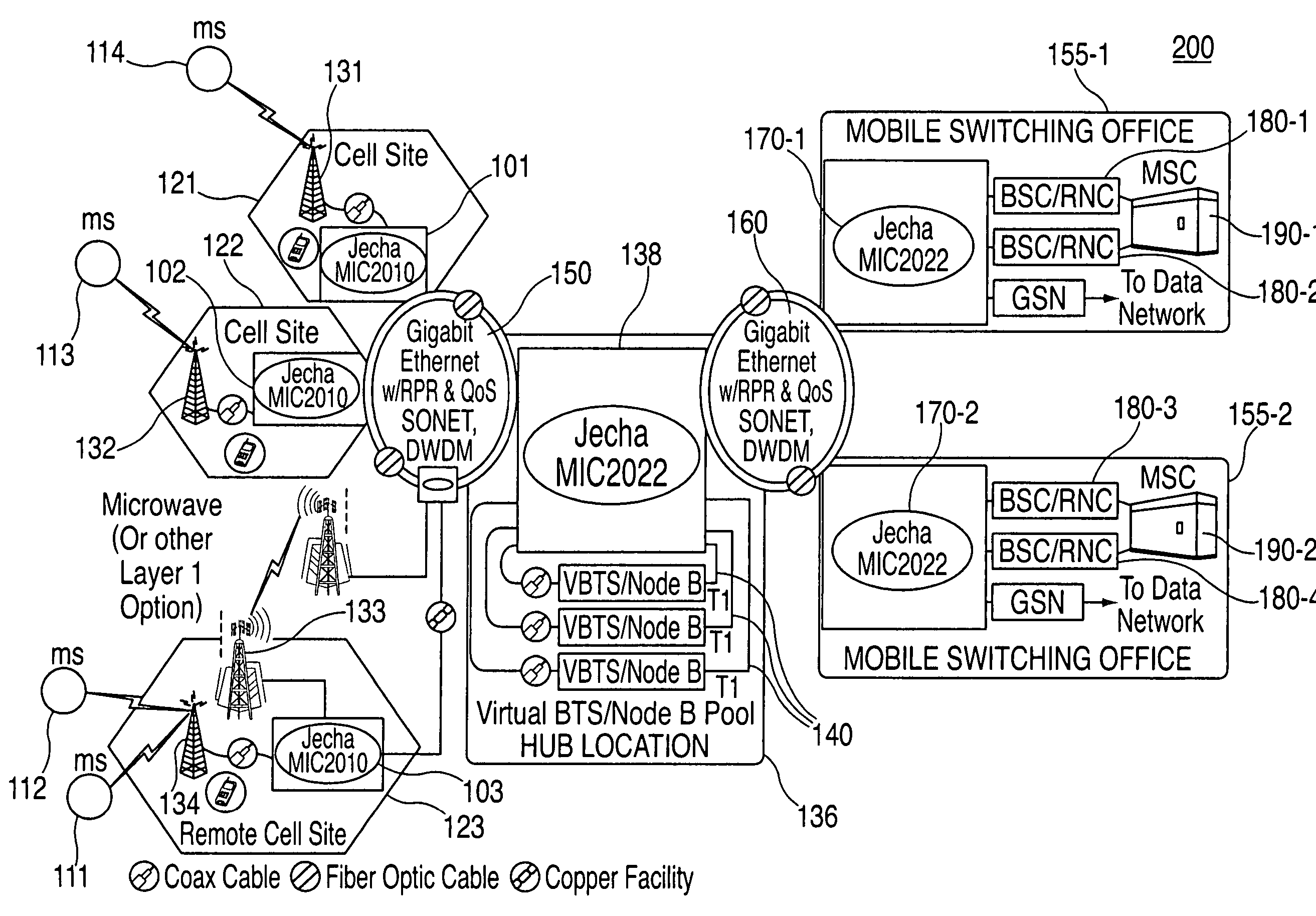
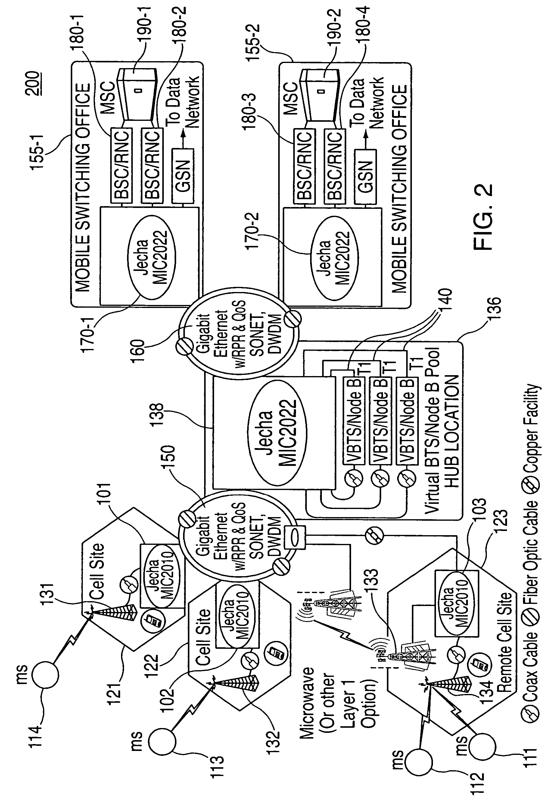
[0036]In accordance with a preferred embodiment of the invention, a communication network provides wireless communication services, such as wireless data communication services, to a plurality of mobile stations operating within the communication network. Stated specifically, in accordance with one aspect, a novel network infrastructure is disclosed for increasing the efficiency of the network. In accordance with another aspect, a continuous network optimization algorithm is disclosed for further enhancing the efficiency of the network in the context of the novel network infrastructure.

[0037]The system of the present invention provides many important advantages and efficiencies over prior systems. By utilizing the novel network infrastructure of the invention, overall operations costs are reduced, sharing of radio and network bandwidth resources is enabled and the reliability of the access network is increased. More specific advantages include the substantial elimination of stranded...


PUM


Abstract

A system and method is disclosed for increasing the efficiency of a cellular communication network, reduce ongoing operating costs and increase revenue. According to one aspect, a method is disclosed for increasing the efficiency of a cellular communication network whereby network capacity in the radio access network (RAN) and baseband processing for wireless connections are dynamically adjusted to automatically provision sufficient bandwidth and baseband processing capacity in response to changes in the network. The method is further extended by implementing policy management which allows wireless carriers to develop and implement network based policies to automatically increase or decrease the amount of processing resources and network bandwidth required from any cell site, hub or mobile switching office. According to another aspect, network efficiency is enhanced by utilizing a novel cellular network infrastructure. RF signals from cell site antennas of various technology types are demodulated, digital bit information is extracted from the RF signals, processed, and groomed into Gigabit Ethernet / Resilient Packet Ring (GigE / RPR) or Ethernet over copper traffic flows using specific Quality of Service (QoS) priorities. The GigE / RPR traffic flows are routed to hub sites or mobile switching offices, at which point the packetized information is extracted and converted to RF signals that are equivalent to the signals that were received at the antenna. The RF signals are sent over coaxial cable to a network hub including a pool of Base Transceiver Stations (BTSs) (or Node Bs). The hub is coupled to one or more mobile switching offices via a second fiber optic ring.

Description

CROSS REFERENCE TO RELATED APPLICATIONS[0001]This is a non-provisional application which claims the priority date of provisional patent application Ser. No. 60 / 445,388 filed on Feb. 6, 2003.TECHNICAL FIELD[0002]The present invention relates generally to improvements to cellular wireless communication networks, and more particularly to a novel network infrastructure and method for increasing efficiency in a cellular wireless communication network.DESCRIPTION OF RELATED ART[0003]Cellular wireless networks are designed to support voice and data services and are generally known to include a “network infrastructure” that facilitates wireless communications with mobile stations operating within a respective service coverage area. The network infrastructure typically includes a plurality of base stations dispersed throughout the service coverage area, each of which supports wireless communications within a respective cell (or set of sectors). The base stations couple to base station contro...

Claims


Application Information

Patent Timeline
Patent Type & Authority Patents(United States)
IPC IPC(8): H04J3/24H04L12/28H04L12/56H04L12/66H04W24/02H04W88/00H04W88/08
CPCH04L12/66H04L47/14H04W24/02H04W88/085H04W88/00H04W28/0289H04W8/04
Inventor CHAMBERS, MAHDIHAZELL, DESMOND
Owner CHAMBERS MAHDI
Why Eureka
Try Eureka