Temperature control using infrared sensing

Inactive Publication Date: 2005-01-11
BEHR AMERICA
View PDF15 Cites 18 Cited by
  • Summary
  • Abstract
  • Description
  • Claims
  • Application Information

AI Technical Summary

Benefits of technology

According to still another aspect of the invention, the controller adjusts the performance of an HVAC compressor based on a signal obtained from the sensor. For example, the signal may be used in a manner that depends on the type of compressor. The controller may c

Problems solved by technology

The controller may cause a fixed compressor to turn off, or alternatively it may reduce performance of a variable displacement compressor, when

Method used


Image

  • Temperature control using infrared sensing
  • Temperature control using infrared sensing
  • Temperature control using infrared sensing

Examples


Embodiment Construction

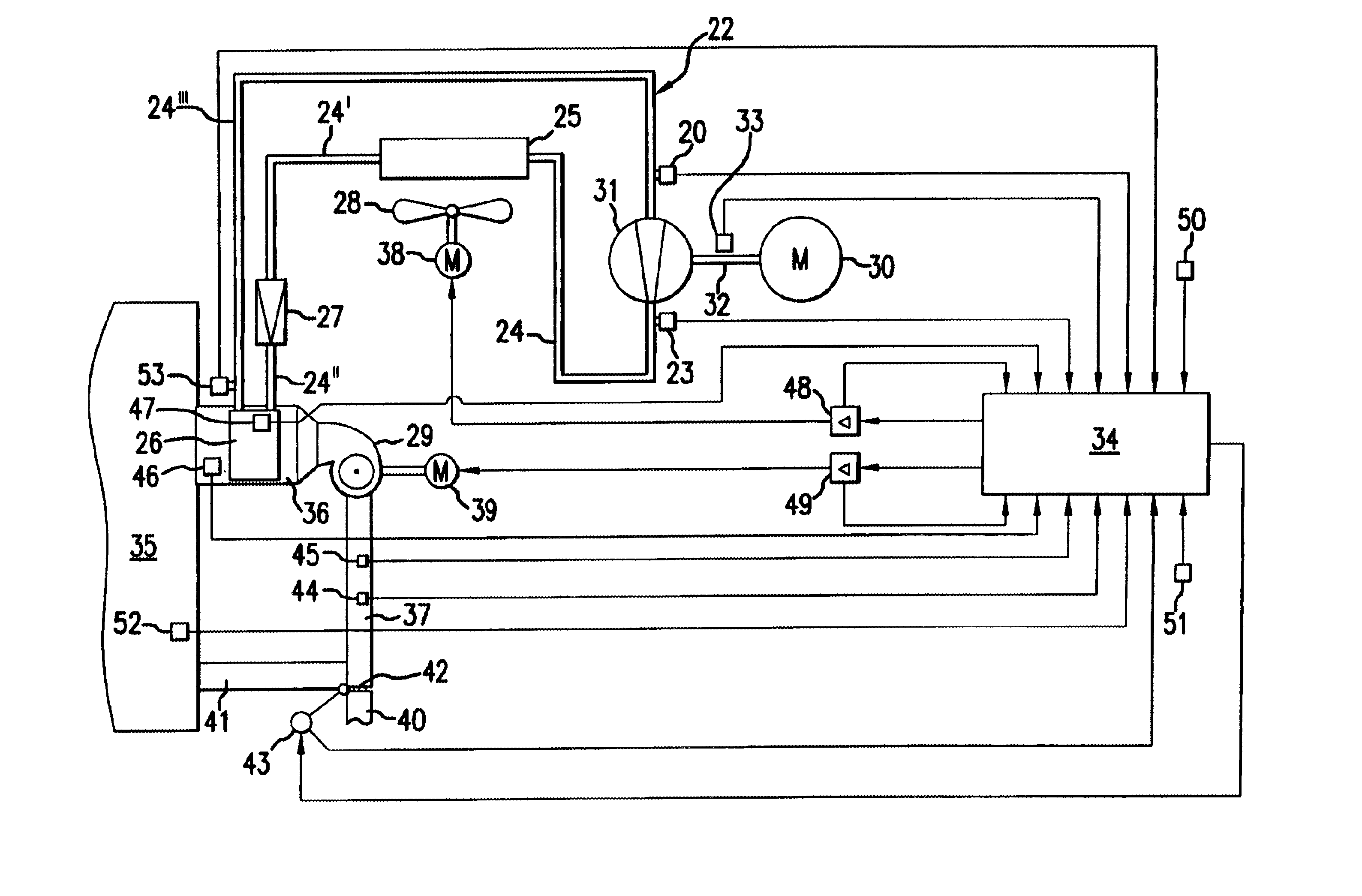
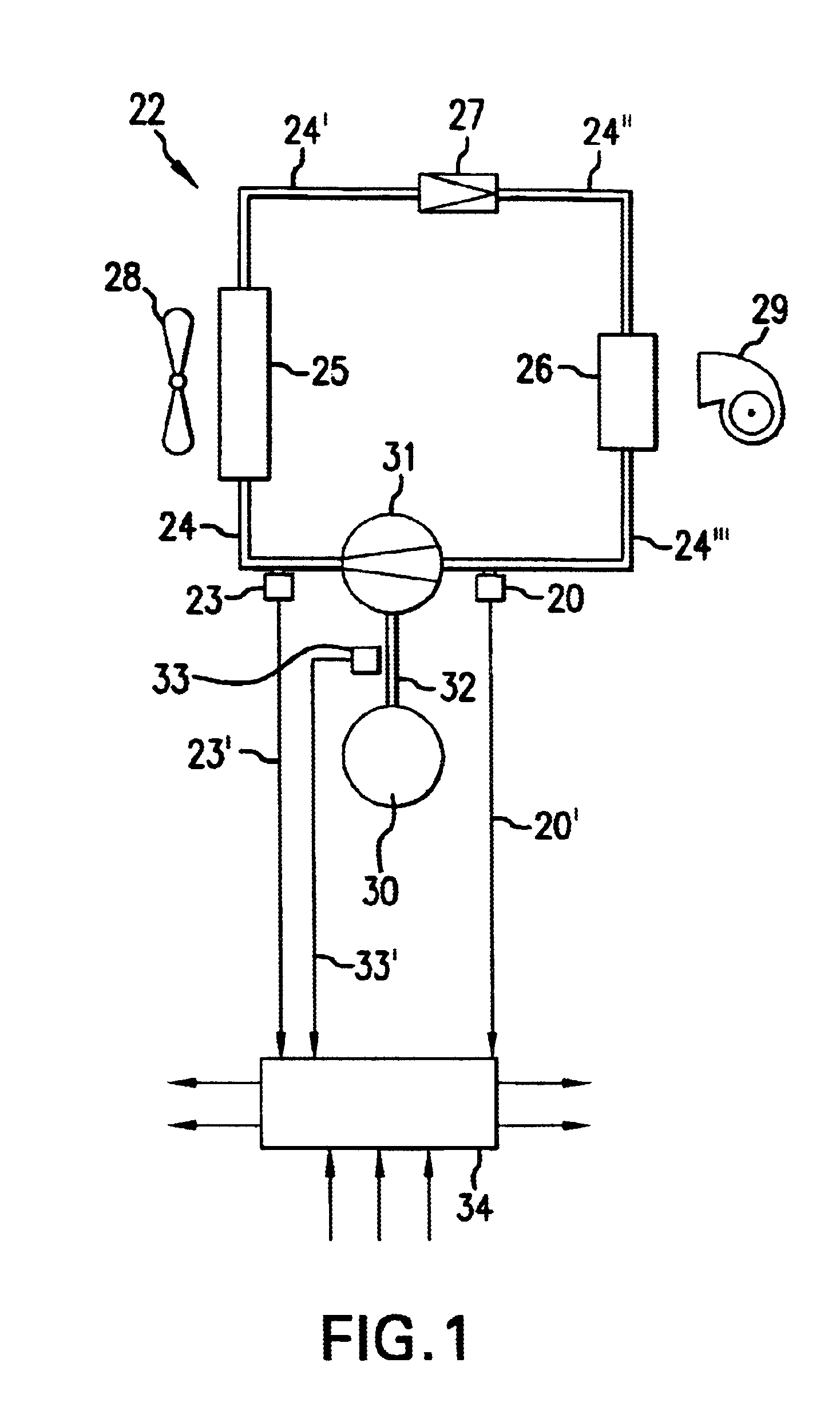
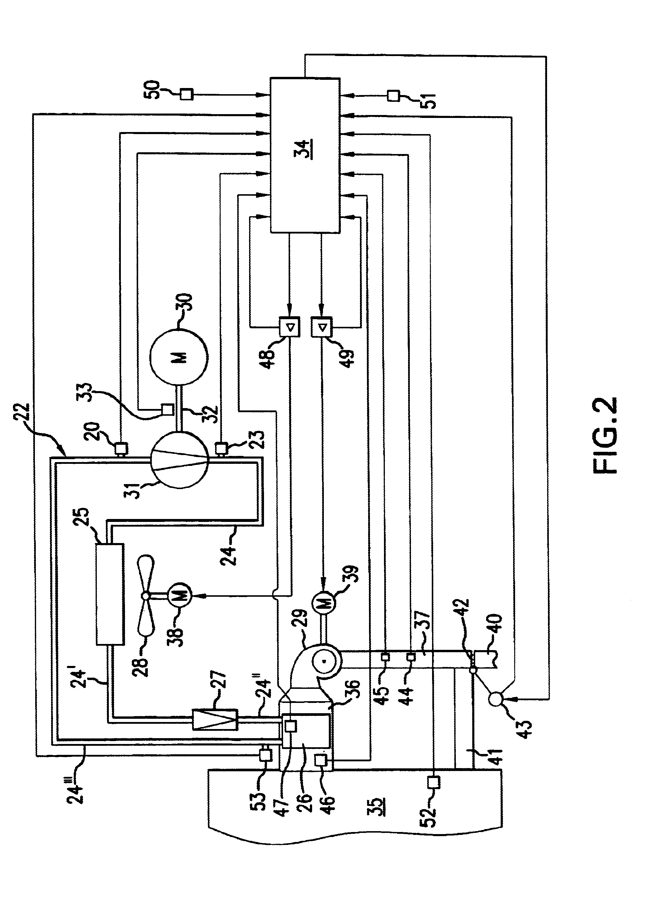
The present invention senses the temperature of the air outlet side of the evaporator using an infrared sensor. Preferably, temperature is measured over several different areas in which a cold spot may occur. More preferably, the infrared sensor continuously scans the whole surface on the air outlet side of the evaporator. The sensed temperature is used to detect any cold spots that may dynamically form on the evaporator surface.

According to one aspect of the invention, the sensed temperature is used to control an HVAC system in a vehicle. More specifically, the system may switch off the compressor in the HVAC system upon detection of one or more cold spots that may cause build-up of ice. Alternatively, the system may reduce the performance of a variable displacement compressor upon detection of one or more cold spots.

The invention provides several distinct advantages. First, by scanning over different areas of the evaporator surface rather than a single fixed location, dynamic cold...


PUM


Abstract

A system and method for sensing and controlling the temperature of a heating, ventilation and air conditioning (HVAC) system utilizes an infrared sensor. The infrared sensor is used to detect temperature over several different areas on an evaporator surface on which a cold spot may occur. More preferably, the infrared sensor continuously scans the whole surface on the air outlet side of the evaporator. The sensed temperature is used to detect any cold spots that may dynamically form on the evaporator surface. The system is controlled in response to the detected temperature.

Description

FIELD OF INVENTIONThis invention relates generally a system and method for sensing and controlling the temperature of a heating, ventilation and air conditioning (HVAC) system. More specifically it relates to a system and method for controlling temperature of a vehicle HVAC system using an infrared (IR) sensor.BACKGROUND OF THE INVENTIONRefrigeration systems, particularly the evaporator coils of refrigerators, air conditioning equipment or heat pump systems, are susceptible to frost accumulation during operation. Frost accumulation is undesirable in that: it decreases the airflow (at times, completely) by blocking the air pass; it decreases the cooling efficiency of the system; it reduces the capacity of the system; and it raises operating cost. The accumulation of ice or frost on evaporator coils in refrigerating equipment is a significant problem. The accumulation insulates the air to be cooled from the cold refrigerating fluid circulating through the evaporator unit, resulting in...

Claims


Application Information

Patent Timeline
IPC IPC(8): G05D23/27B60H1/32F24F11/02F25D21/02
CPCB60H1/321G05D23/27F25D21/02B60H2001/3261F25B2700/11F25B2700/171F25B2700/1931F25B2700/2117F25B2700/21173F25B2700/21175F25B2700/1933B60H2001/00961
Inventor LINDNER, BJOERNTA, THIEN D.
Owner BEHR AMERICA
Why Eureka
Try Eureka