Pinch detection system

Inactive Publication Date: 2005-01-11
CONTINENTAL AUTOMOTIVE SYST INC
View PDF8 Cites 45 Cited by
  • Summary
  • Abstract
  • Description
  • Claims
  • Application Information

AI Technical Summary

Benefits of technology

By updating the reference value and based on the actual force characteristics of the moving object and changing the pinch threshold based on the reference value, the inventive system ensures accurate

Problems solved by technology

Customizing the force profile for each individual object is time-consuming and costly, so some current systems use a pre-determined reference field that is obtained from a theoretical design value or a pre-calculated average of force profiles from several samples.
Even with these calculations, manufacturing variances from object to object will create inevitable errors between the predetermined

Method used


Image

  • Pinch detection system
  • Pinch detection system
  • Pinch detection system

Examples


Embodiment Construction

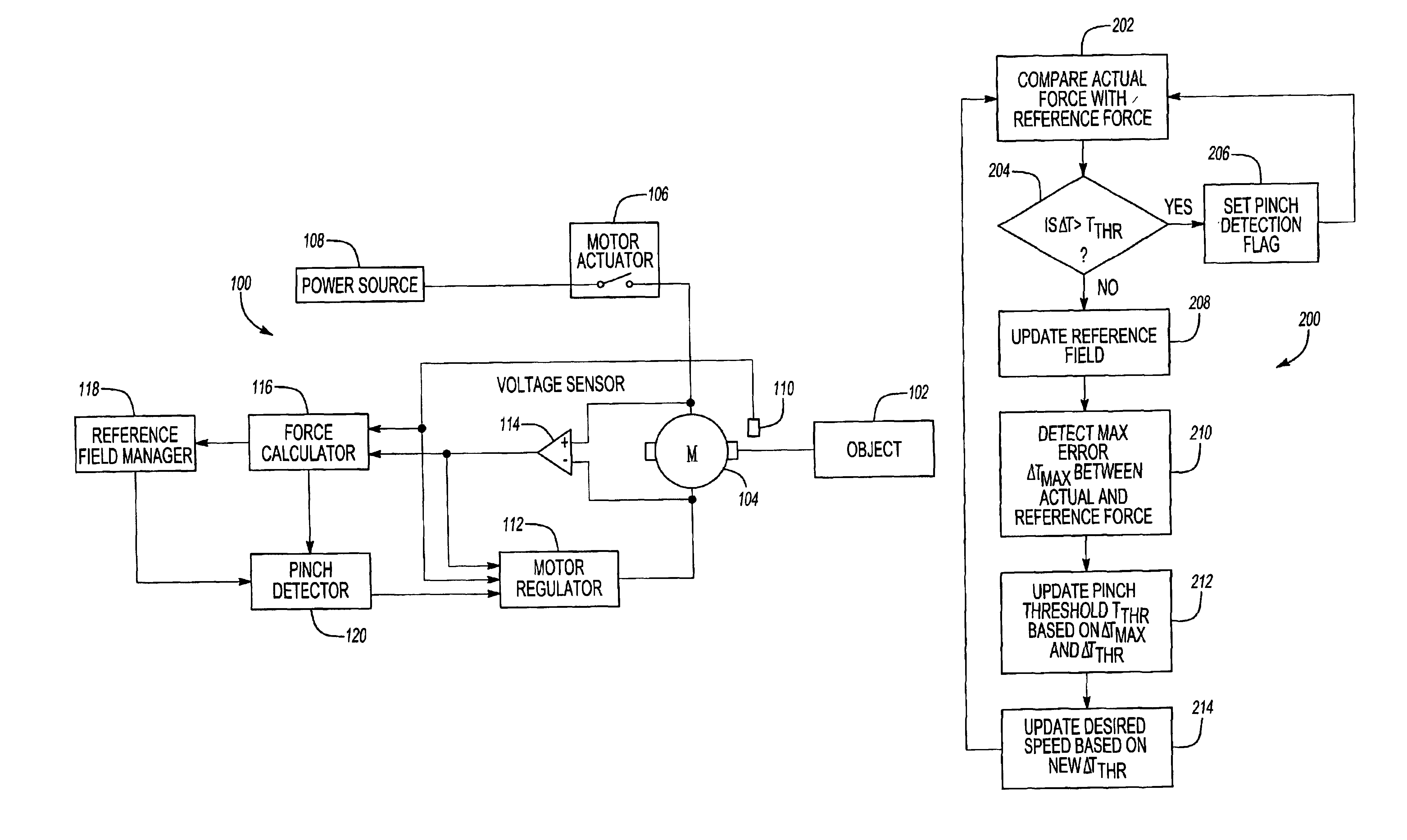
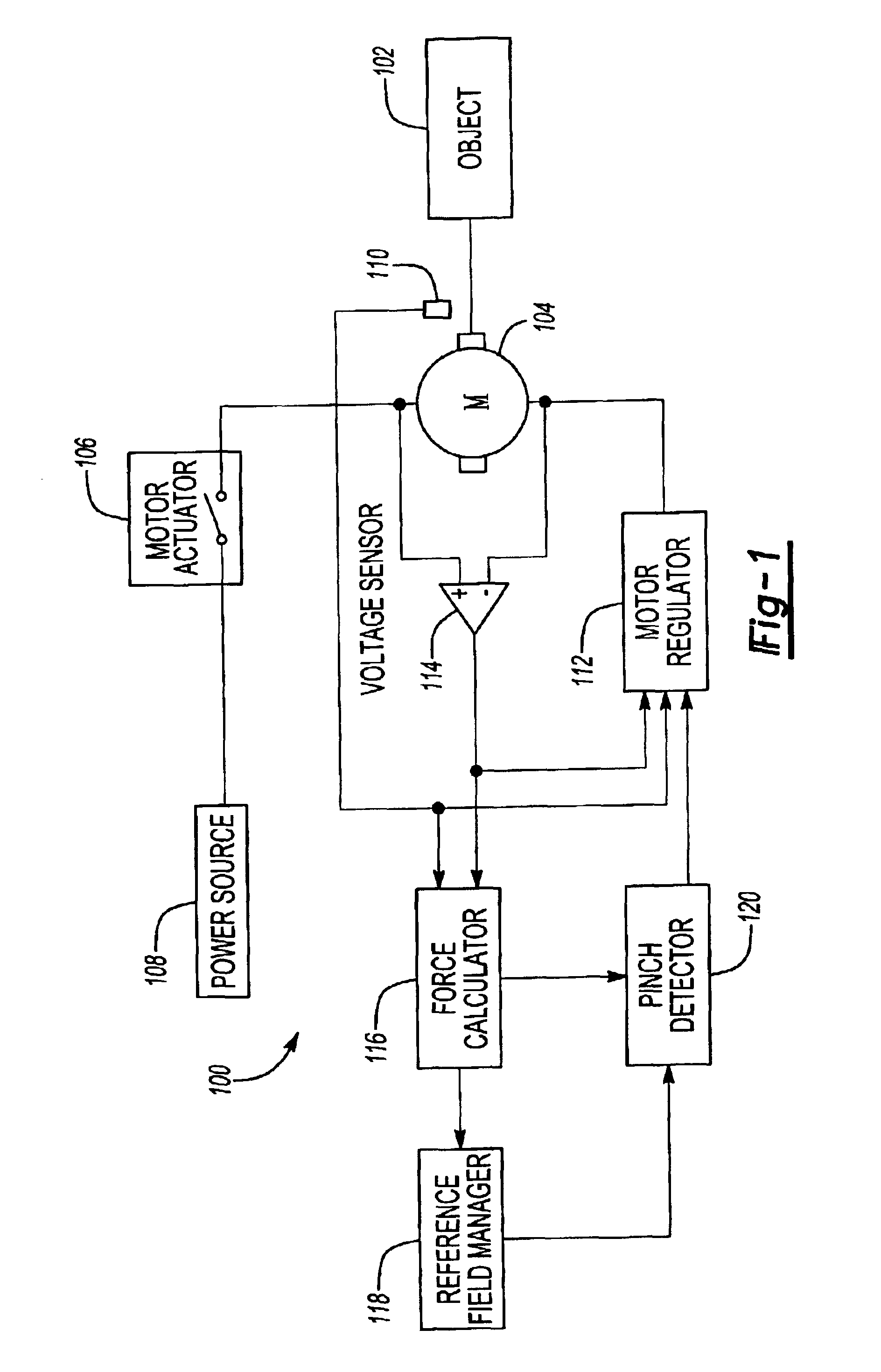
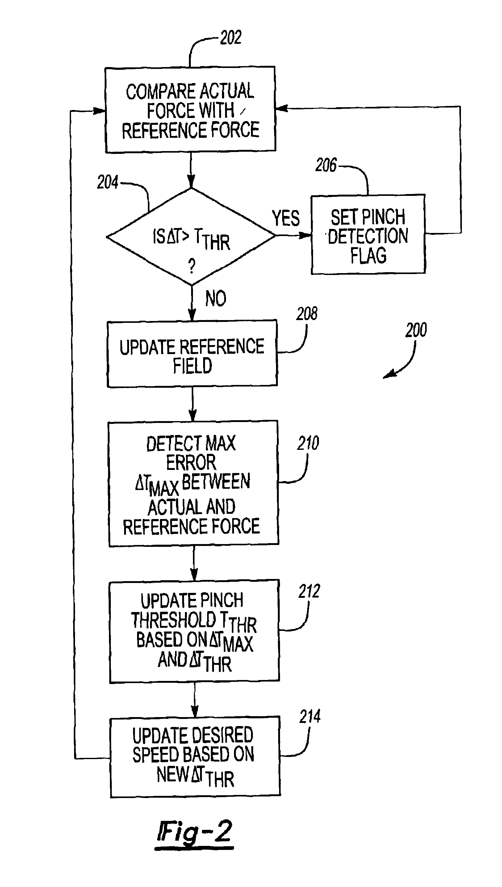
FIG. 1 is a schematic diagram illustrating a pinch detection system 100 according to one embodiment of the invention. The system 100 controls power movement of an object 102, such as a vehicle window, vehicle door, trunk, lift gate, sliding door, etc. Although the example shown in the figures and described below focuses on moving a vehicle component, the object 102 moved by the system 100 can be any object 102 movable by a motor.

The system 100 includes a motor 104 that is actuatable by a motor actuator 106, such as a bi-directional relay, H-bridge power transistor or other actuation device. The motor actuator connects and disconnects the motor 104 to and from a power source 108. A speed sensor 110 detects the rotational speed of the motor 104. The speed sensor 110 can be any type of speed sensor appropriate for monitoring the speed of the motor 104, such as an encoder, Hall effect sensor, or other type of sensor. In one embodiment, the speed sensor 110 sends an output to a motor reg...


PUM


Abstract

A pinch detection system and method controls the speed of a motor moving an object by first calculating the actual motor force and then comparing the actual motor force with a reference force value in a reference field. A pinch condition is indicated if the difference between the actual force and the reference force exceeds a selected pinch threshold. The difference is also used to update the reference field, the pinch threshold and the desired speed of the motor so that the reference field will eventually reflect the actual force profile of the object. The updated pinch threshold is also used to control the motor speed so that the pinching force remains constant regardless of the pinch threshold value.

Description

TECHNICAL FIELDThe present invention is directed to a control system for a power-operated moving object, such as a vehicle window more particularly to a control system that detects a possible pinch condition in the moving object.BACKGROUND OF THE INVENTIONSystems for moving objects (e.g., sliding vehicle doors, lift gates, trunks, windows, and the like) often incorporate a pinch detection system that detects when a obstacle is in the path of the moving object. Currently known systems compare the motor force or torque with a reference force or torque and determines that a pinch condition exists if the actual force is greater than the reference force by a certain amount.The reference force used to detect the pinch condition is normally obtained from a reference field that ideally represents the force profile of the moving object. Customizing the force profile for each individual object is time-consuming and costly, so some current systems use a pre-determined reference field that is o...

Claims


Application Information

Patent Timeline
IPC IPC(8): H02H7/085H02H3/00
CPCH02H7/0851H02H3/006
Inventor FUKUMURA, TOMOHIROMARLETT, BRIAN J.DASH, SANJAYA KUMAR
Owner CONTINENTAL AUTOMOTIVE SYST INC
Why Eureka
Try Eureka