Multi-disk friction device selective lubrication on demand

US6840363B2Inactive Publication Date: 2005-01-11BORGWARNER INC

Image

  • Multi-disk friction device selective lubrication on demand
  • Multi-disk friction device selective lubrication on demand
  • Multi-disk friction device selective lubrication on demand

Examples


Embodiment Construction

)

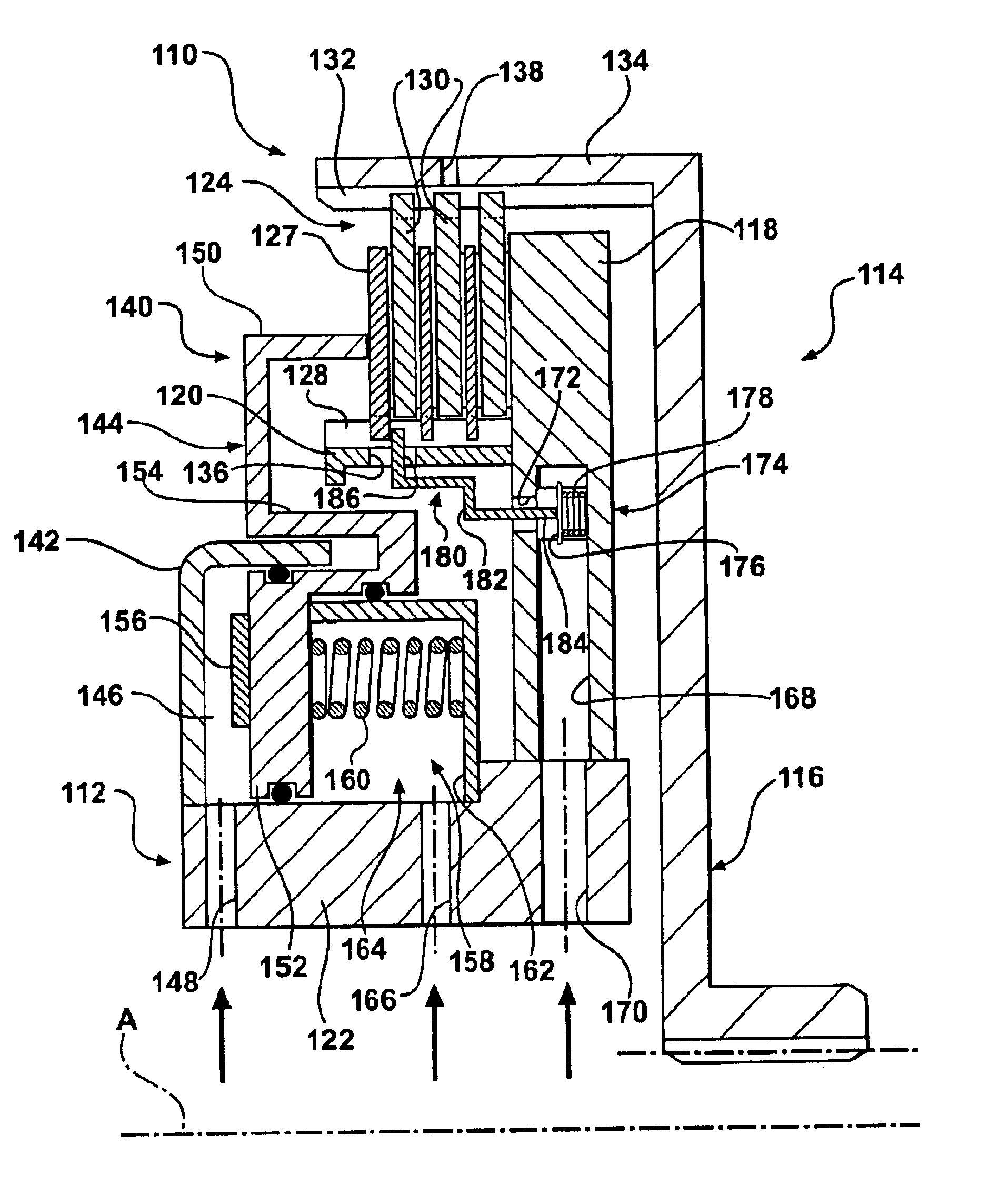
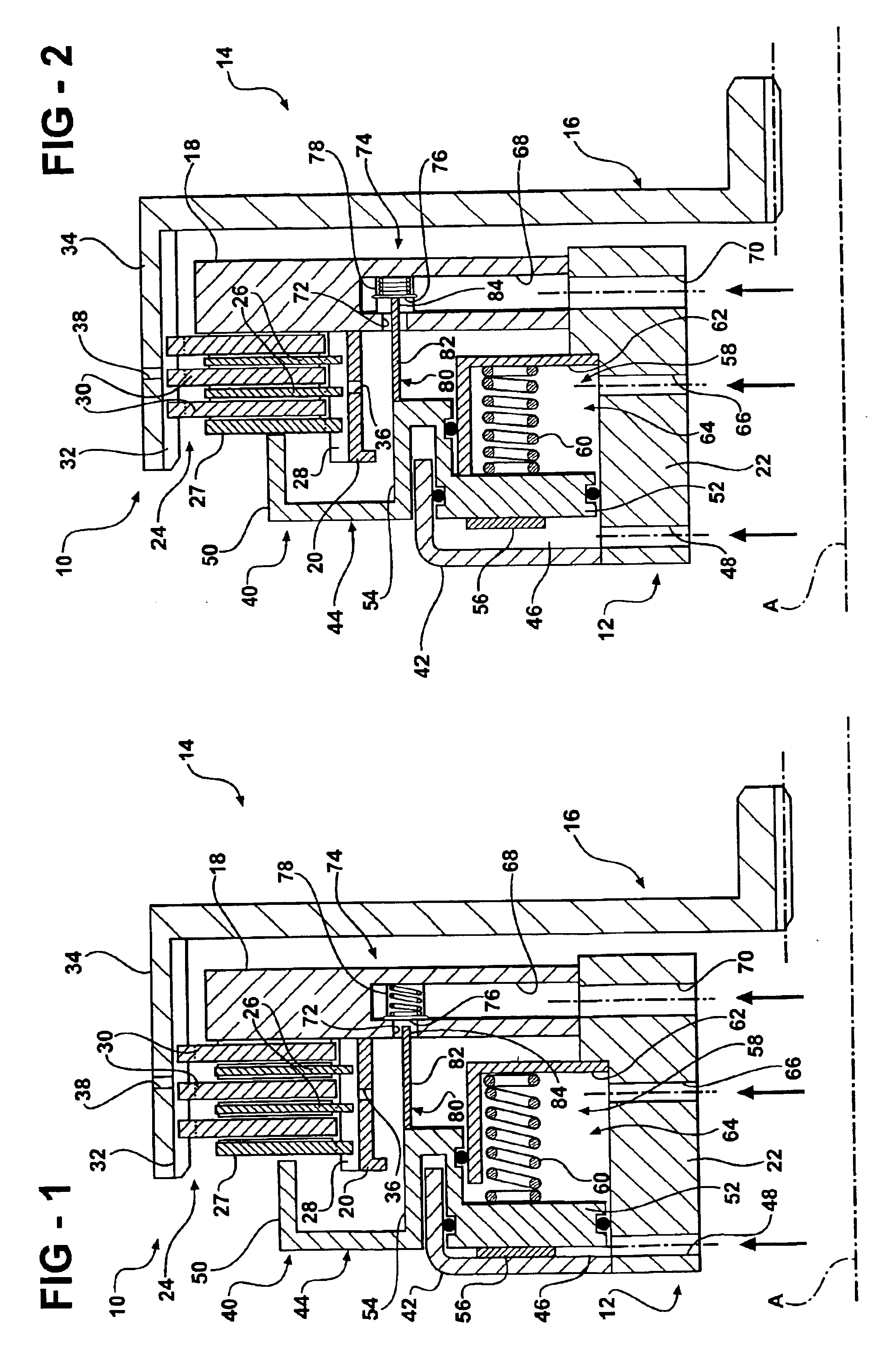
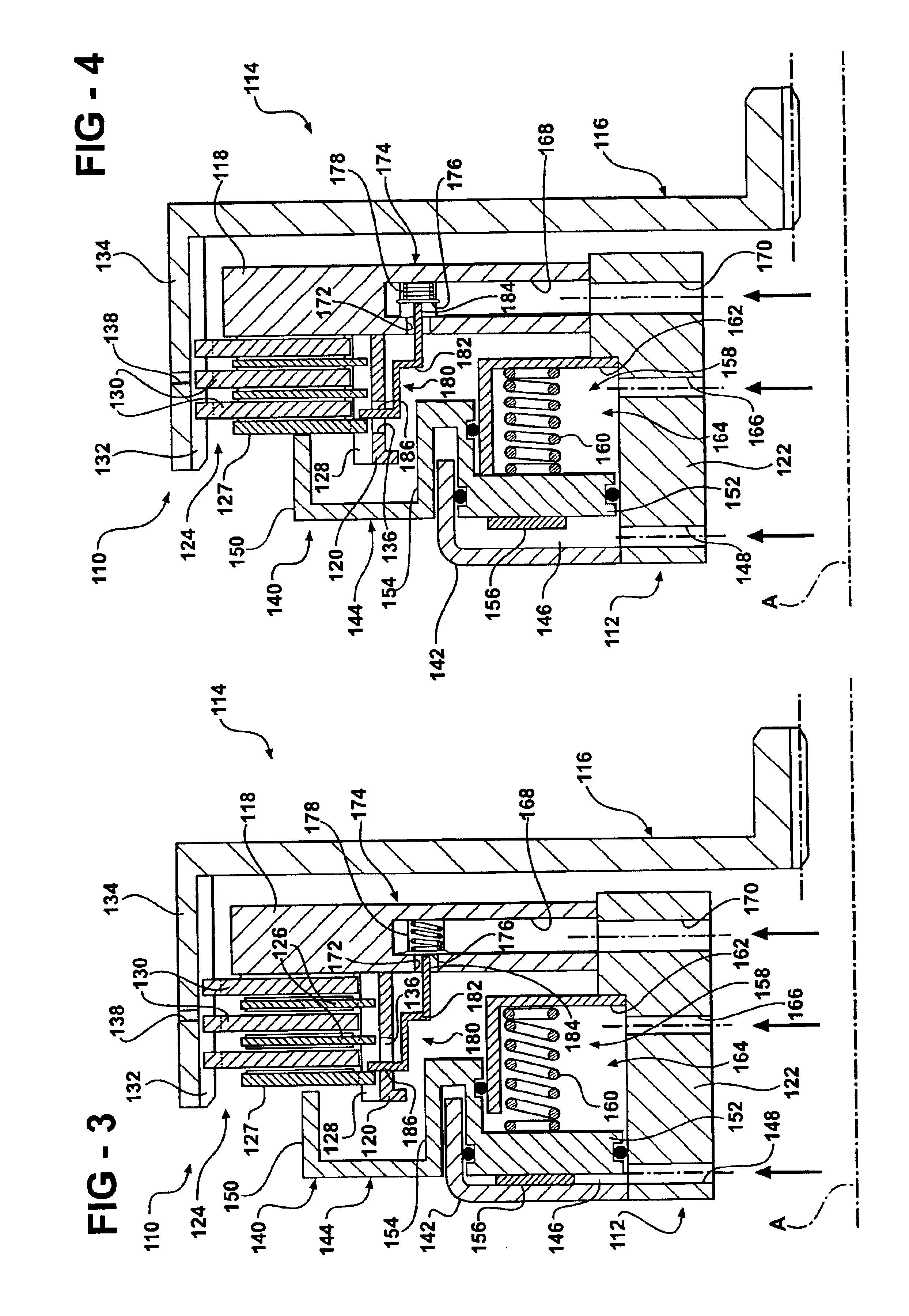
Referring now to FIG. 1, a friction device such as a clutch or brake assembly of the present invention is generally indicated at 10. The friction device 10 is adapted to be employed in connection with a transmission, differential or brake system. For example only and not by way of limitation, as is commonly known in the art, but not shown in these figures, transmission assemblies typically include an input shaft which is operatively coupled to a prime mover, such as an internal combustion engine. In an automotive application, the transmission assembly also includes an output shaft which is operatively coupled to driven wheels through other drivetrain components such as a drive shaft and an axle having a differential. At least one, and often a plurality of, gear sets is operatively coupled between the input and output shafts. The transmission casing supports the input shaft, the output shaft and the gear sets of the transmission assembly.

Various components of the gear sets are held ...


PUM


Abstract

A friction device (10, 110) having a drive member (12, 112) and a driven member (14, 114) which define a clutch housing (16, 116) therebetween. A clutch pack (24, 124) is interposed between the drive and driven members and is operable to connect and disconnect the drive and driven members for transferring and interrupting torque therebetween. A control valve (74, 174) is supported in the clutch housing (16, 116) and is moveable between open and closed positions. The control valve (74, 174) is operable to control the flow of cooling fluid from the source to the clutch pack (24, 124). The friction device also includes an actuator (80, 180) that is operatively connected to either a piston assembly (40) or the clutch pack (124) and is adapted to engage the control valve (74, 174) such that movement of the piston assembly (40) from its disengaged position to its engaged position moves the control valve (74, 174) from its closed position to its open position to selectively allow flow of pressurized cooling fluid past the control valve (74, 174) and into contact with the clutch pack (24, 124) when the drive and driven members are connected.

Description

BACKGROUND OF THE INVENTION1. Field of the InventionThe present invention relates, generally, to friction devices such as clutch or brake assemblies for use in transmissions, differentials or brake systems. More specifically, the present invention relates to a multi-disk friction clutch or brake systems having selectively actuated lubrication for cooling the clutch on demand.2. Description of the Related ArtMulti-disk friction devices are employed in a wide range of applications as clutches or brakes. For example, such friction devices are frequently used in land-based vehicles. Generally speaking, land vehicles require three basic components. These components include a power plant (such as an internal combustion engine), a powertrain, and wheels. The powertrain's main component is typically referred to as the “transmission.” Engine torque and speed are converted in the transmission in accordance with the tractive-power demand of the vehicle. Transmissions include one or more gear s...

Claims


Application Information

Patent Timeline
11 Jan 2005
Publication
US6840363B2
IPC
F16D25/06; F16D13/52; F16D13/58; F16D13/00; F16D13/72; F16D25/0638; F16D65/78; F16D65/00
CPC
F16D13/52; F16D25/0638; F16D13/72; F16D2065/783; F16D25/123
Inventors
BRAFORD, JR., THOMAS E.; SCHMIDT, THOMAS