
MRI systems with parallel receivers for phase correction

a phase correction and receiver technology, applied in the field of magnetic resonance imaging apparatus, can solve the problems of ghosts generated in the reconstructed image, inconsistency with the sensitivity matrix,

Inactive Publication Date: 2005-01-11
GE MEDICAL SYST GLOBAL TECH CO LLC
View PDF12 Cites 16 Cited by
  • Summary
  • Abstract
  • Description
  • Claims
  • Application Information

AI Technical Summary

Benefits of technology

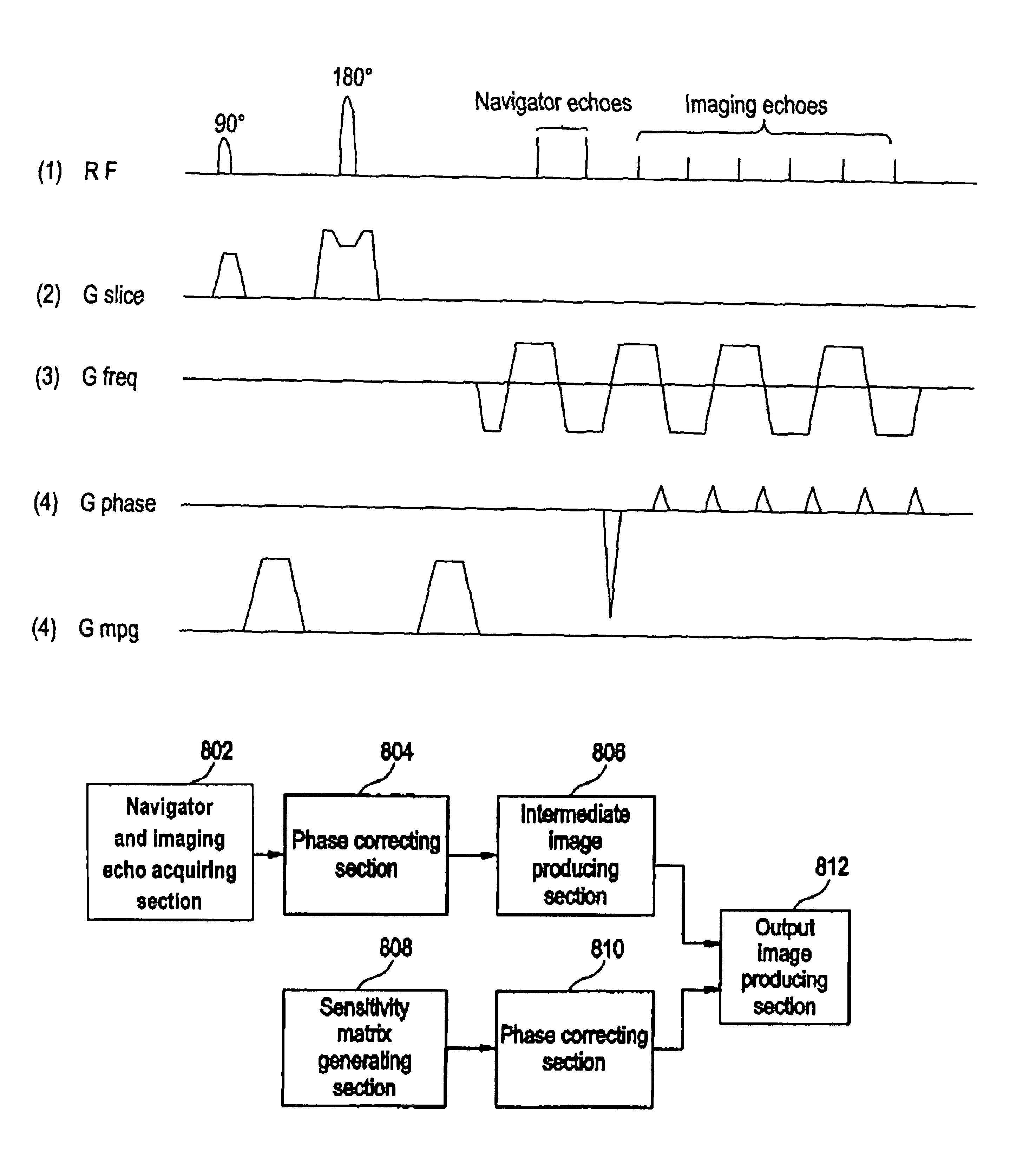
It is therefore an object of the present invention to provide a magnetic resonance imaging apparatus that enables parallel imaging even when a navigator echo is used to phase-correct an imaging echo.
In the present invention, matrix data in a sensitivity matrix are phase-corrected, and therefore, inconsistency with an imaging echo that is phase-corrected using a navigator echo is eliminated and an image can be correctly produced.
The second correcting means preferably homogenizes the phase so that consistency with the phase correction on the imaging echo may be improved. The phase may be zero or a constant value other than zero.
Therefore, the present invention provides a magnetic resonance imaging apparatus that enables parallel imaging even when a navigator echo is used to phase-correct an imaging echo.

Problems solved by technology

If positional shifting of the spins occurs between the excitations due to pulsation of the brain in such a process, a phase error between the imaging echoes leads to ghosts generated in the reconstructed image.
This is because when the imaging echoes are phase-corrected by the navigator echo, the phase originating from the sensitivity of the receiver systems is unnecessarily corrected, resulting in inconsistency with the sensitivity matrix.

Method used


Image

  • MRI systems with parallel receivers for phase correction
  • MRI systems with parallel receivers for phase correction
  • MRI systems with parallel receivers for phase correction

Examples


Embodiment Construction

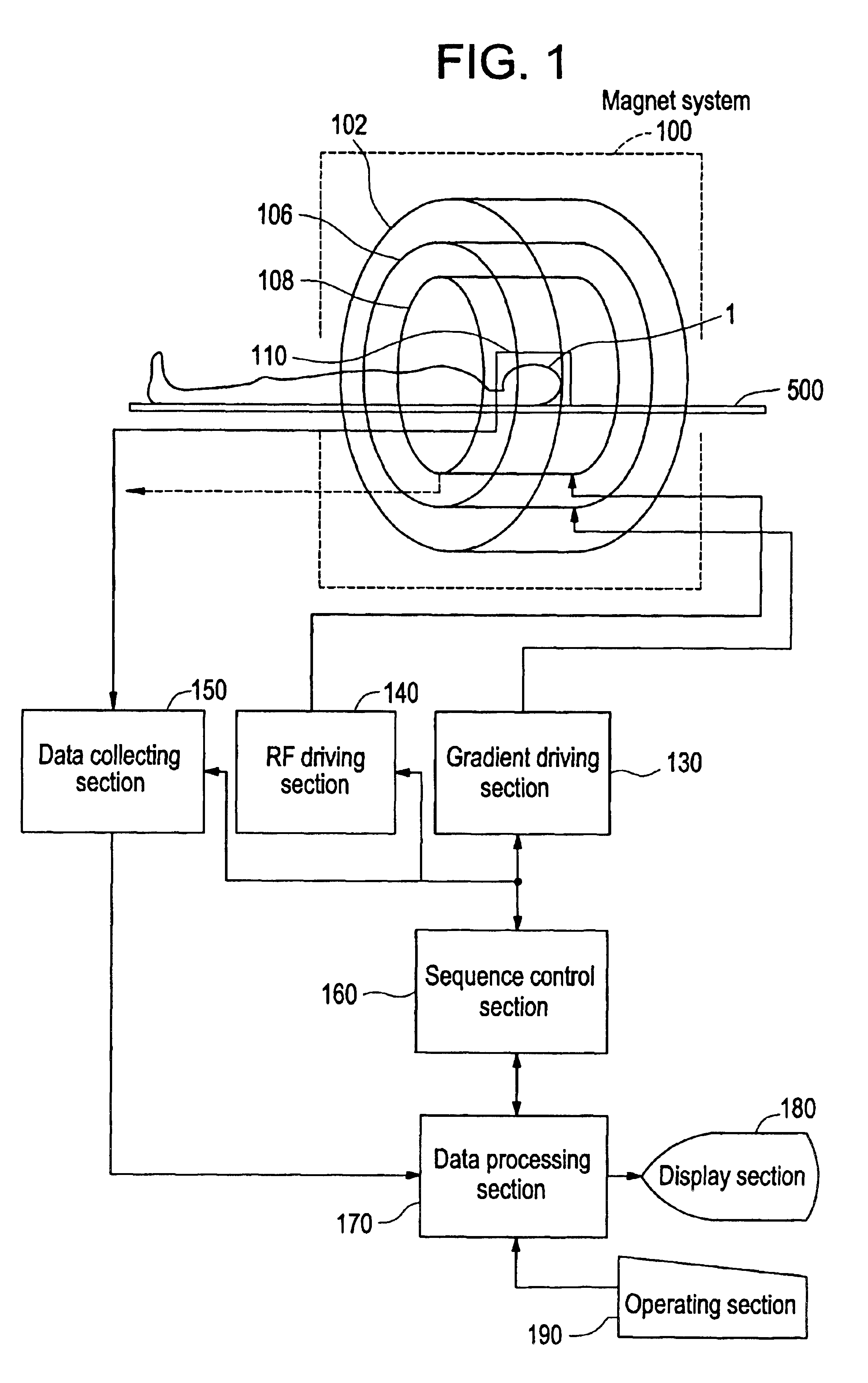
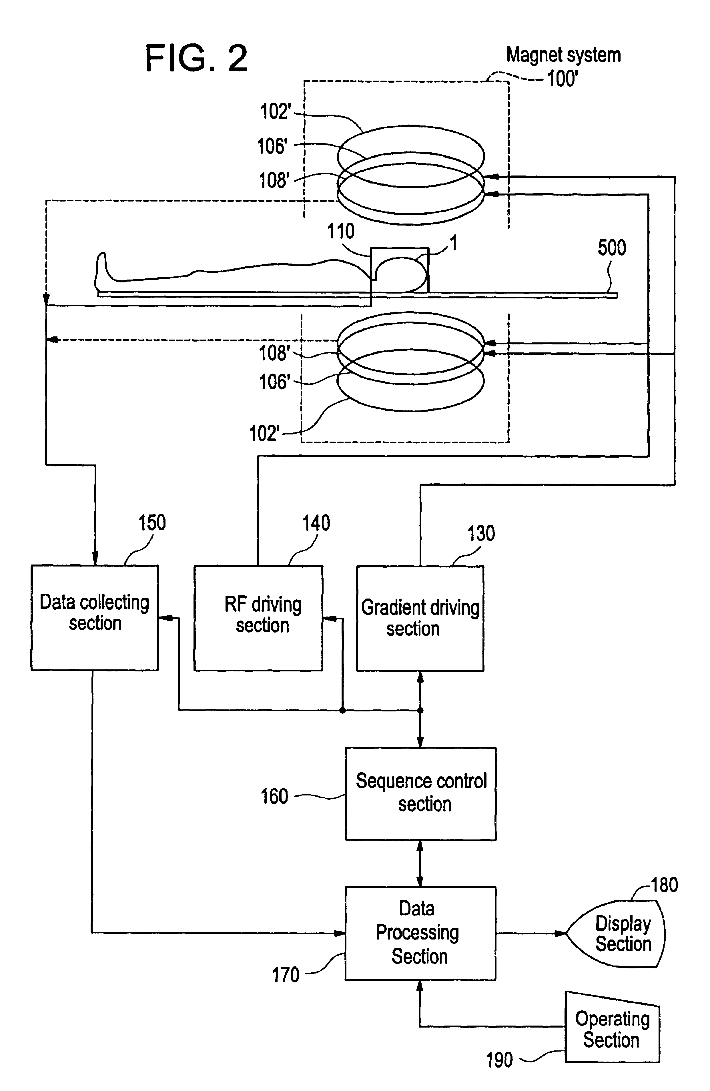
Embodiments of the present invention will now be described in detail with reference to the accompanying drawings. FIG. 1 shows a block diagram of a magnetic resonance imaging apparatus, which is an embodiment of the present invention. The configuration of the apparatus represents an embodiment of the apparatus in accordance with the present invention.

As shown in FIG. 1, the present apparatus has a magnet system 100. The magnet system 100 has a main magnetic field coil section 102, a gradient coil section 106, and an RF coil section 108. These coil sections have a generally cylindrical shape and are concentrically disposed. A subject to be imaged 1 is rested on a cradle 500 and carried into and out of a generally cylindrical internal space (bore) of the magnet system 100 by carrier means, which is not shown.

The head of the subject 1 is fitted with a receiving coil section 110. The receiving coil section 110 has a plurality of receiving coils. The receiving coil section 110 will be de...


PUM


Abstract

For the purpose of enabling parallel imaging even when a navigator echo is used to phase-correct an imaging echo, the present invention involves: exciting spins within a subject to acquire an imaging echo generated by the excited spins along with a navigator echo, with a reduced field-of-view via a plurality of receiver systems; conducting phase correction on the imaging echo based on the navigator echo; producing an intermediate image based on the phase-corrected imaging echo from each of the plurality of receive systems; generating a sensitivity matrix for the plurality of receiver systems; correcting the phase of matrix data in the sensitivity matrix; and producing an image with a full field-of-view based on the intermediate image and the phase-corrected sensitivity matrix.

Description

CROSS REFERENCE TO RELATED APPLICATIONSThis application claims the benefit of Japanese Application No. 2002-238971 filed Aug. 20, 2002.BACKGROUND OF THE INVENTIONThe present invention relates to a magnetic resonance imaging apparatus, and more particularly to a magnetic resonance imaging apparatus that conducts parallel imaging.In a magnetic resonance imaging (MRI) apparatus, a subject to be imaged is carried into an internal space of a magnet system, i.e., an imaging space in which a static magnetic field is generated, a gradient magnetic field and a radio frequency (RF) magnetic field are applied to excite spins within the subject to thereby generate magnetic resonance signals, and an image is reconstructed based on the received signals.One scheme of the magnetic resonance imaging is parallel imaging. Parallel imaging is described by, for example, Klaas P. Pruessmann et al. in an article entitled “SENSE: Sensitivity Encoding for Fast MRI”, Magnetic Resonance in Medicine, 42: 952-9...

Claims


Application Information

Patent Timeline
Patent Type & Authority Patents(United States)
IPC IPC(8): G01R33/561G01R33/54A61B5/055G01R33/48
CPCG01R33/56554G01R33/5611A61B5/055
Inventor IKEZAKI, YOSHIKAZU
Owner GE MEDICAL SYST GLOBAL TECH CO LLC
Learn More