
Fourpoint antenna

a four-point antenna and antenna technology, applied in the direction of resonant antennas, polarised antenna unit combinations, protective material radiating elements, etc., can solve the problems of narrow impedance bandwidth of wire dipoles and monopoles, pattern degradation at the high end of their impedance bandwidth, radiation patterns of circular disc antennas degraded at the high end of the band, etc., to improve the performance of foursquare antennas without increasing mechanical size, and improve the performance of foursquare antenna

Inactive Publication Date: 2005-01-11
VIRGINIA TECH INTPROP INC
View PDF5 Cites 34 Cited by
  • Summary
  • Abstract
  • Description
  • Claims
  • Application Information

AI Technical Summary

Benefits of technology

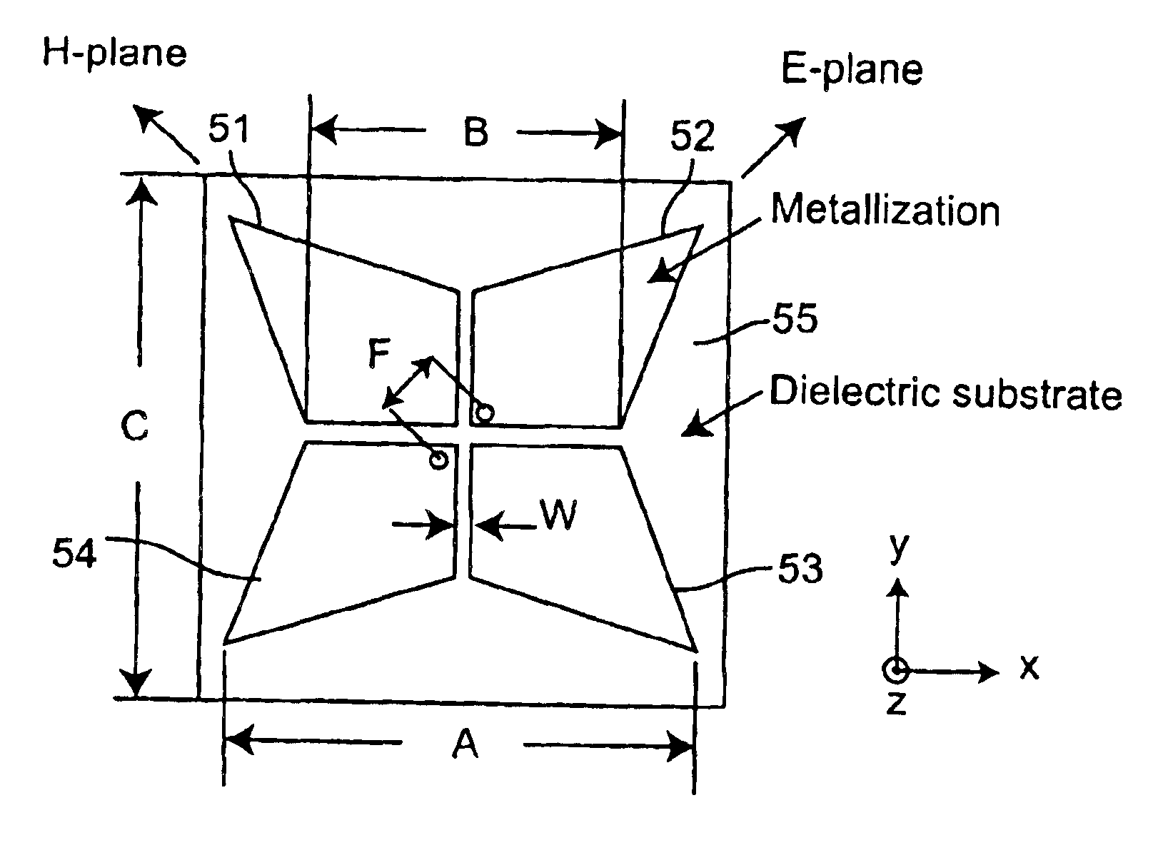
The present invention provides new, compact antenna structures with significantly improved antenna performance over the prior art antennas. The invention includes a new monopole antenna called the Planar Inverted Cone Antenna (PICA) and its variations, which offer several advantages over previous monopole antennas. The PICA has a simple geometry, provides outstanding impedance and radiation pattern performance, and has very low cross polarization. The invention also includes a new Fourpoint antenna which improves the performance of the Foursquare antenna dramatically without increasing mechanical size. The addition of a tuning plate increases the bandwidth and achieves balanced impedance over the operating band and dual polarization over its operating frequency. The Fourpoint antenna has been designed, modeled, constructed, and measured at VTAG, and the computed and measured data are presented to validate the enhanced performance of the Fourpoint antenna. Variations of the Fourpoint and Foursquare antennas also reduce the antenna size and are useful for elements in an array system.

Problems solved by technology

However, the wire dipole and monopole suffer from narrow impedance bandwidth.
However, most such antennas suffer from pattern degradation at the high end of their impedance bandwidth.
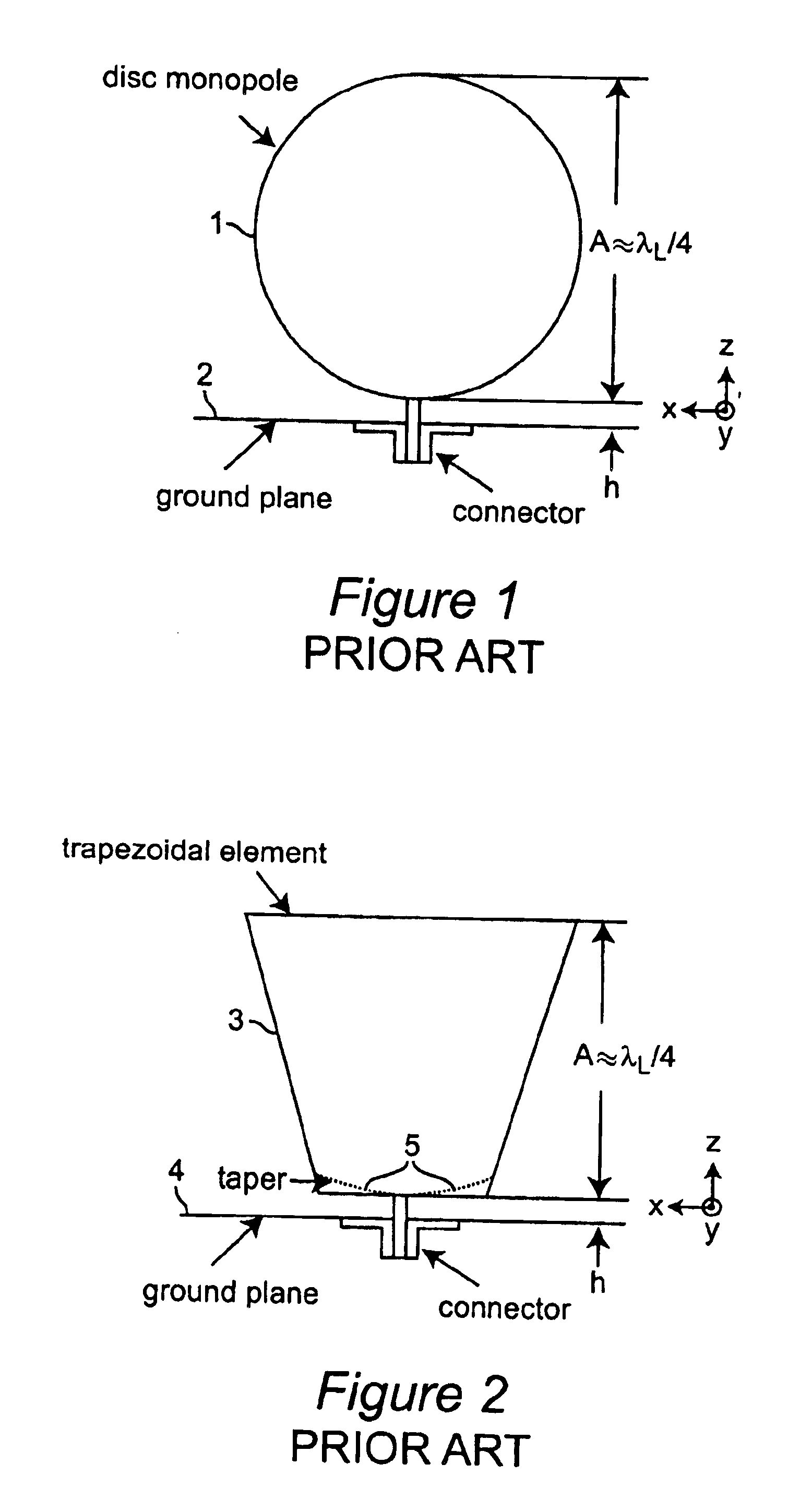
However, the radiation patterns of the circular disc antenna degrade at the high end of the band.
However, the modified flat monopole antennas still suffer from radiation pattern degradation in E-plane.
However, the trapezoidal flat monopole antenna does not solve the problem of variations in tilt angle of the E-plane pattern peak.

Method used


Image

  • Fourpoint antenna
  • Fourpoint antenna
  • Fourpoint antenna

Examples


second embodiment

[0085]FIG. 29A is a top view showing a variation of the Foursquare radiating elements according to a further modification of the invention; and

[0086]FIG. 29B is a top view showing a further variation of the Fourpoint radiating elements according to another modification of the second embodiment of the invention.

DETAILED DESCRIPTION OF THE PREFERRED EMBODIMENTS OF THE INVENTION

[0087]Referring now to FIGS. 4A and 4B of the drawings, there is shown the geometries of the antenna according to the first embodiment of the invention. This embodiment is based on the conventional circular disc antenna of FIG. 1 and has similar impedance bandwidth and improved antenna pattern, but has smaller area than the circular disc antenna. FIG. 4A shows a general geometry of the antenna according to the first embodiment of the invention. The antenna comprises a radiating element 21 having a shape of a truncated inverted cone intersecting an elliptical curve. This radiating element is positioned above and ...

first embodiment

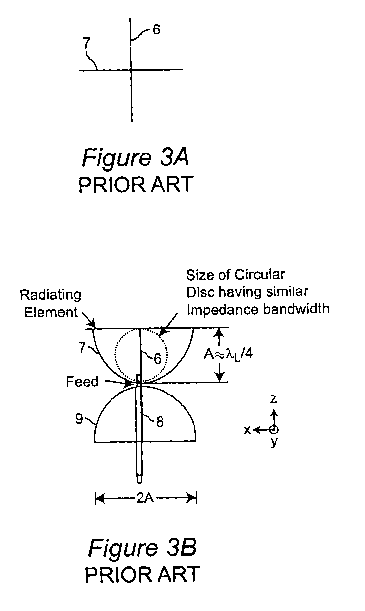
[0092]A modification of the present invention is the Crossed Planar Inverted Cone Antenna (Crossed PICA). The idea of crossed planar discs in a monopole configuration was investigated by Taylor in R. M. Taylor, “A broadband Omnidirectional Antenna,” IEEE Antennas and Propagation Society International Symposium Digest (Seattle), Vol. 2, pp. 1294-1297, June 1994 with the goal of improving the antenna radiation pattern. A crossed half disc antenna with dimension A=50.8 mm in FIG. 3 was simulated to determine the level of cross-polarization. Representative computed patterns at 5 GHz in FIGS. 8A and 8B show co-pol and cross-pol components for angles φ=40° and φ=90°.

[0093]Even though the single PICA has excellent co- and cross-polarized antenna patterns, a crossed PICA antenna was examined to see if even lower cross-pol content could be achieved. The geometry of the crossed PICA antenna is shown in FIG. 9. The antenna has two elements 31 and 32 of the same size and shape that are perpendi...


PUM


Abstract

Wideband antennas with omnidirectional coverage have both military and commercial applications. In one embodiment, the Planar Inverted Cone Antenna (PICA) is composed of a single flat element vertically mounted above a ground plane. A geometry of Planar Inverted Cone Antenna (PICA) is based on the conventional circular-disc antenna with trimmed top part having the shape of a planar-inverted cone, in a second embodiment, the Fourpoint antenna also provides balanced impedance over the operating band and has useful radiation patterns and dual polarization over its operating frequency.

Description

CROSS REFERENCE TO RELATED APPLICATIONS[0002]This patent application is based on provisional patent applications Ser. No. 60 / 354,479 filed Feb. 8, 2002, by Seong-Youp Suh and Warren L. Stutzman for “Planar Inverted Cone Antenna”, and Ser. No. 60 / 354,475 filed Feb. 8, 2002, by Seong-Youp Suh and Warren L. Stutzman for “Fourpoint Antenna”, the complete contents of which are herein incorporated herein by reference.DESCRIPTIONBACKGROUND OF THE INVENTION[0003]1. Field of the Invention[0004]The present invention generally relates to wideband antennas with compact and planar geometry and, more particularly, to planar inverted cone and fourpoint antennas.[0005]2. Background Description[0006]The need for wideband antennas with omnidirectional coverage is increasing in military and commercial applications. Thin antennas are preferred in most situations. The classic solution is to obtain an omnidirectional pattern uses a thin wire dipole or its counterpart monopole version with a ground plane ...

Claims


Application Information

Patent Timeline
Patent Type & Authority Patents(United States)
IPC IPC(8): H01Q1/38H01Q21/24H01Q9/04H01Q21/26H01Q9/28H01Q9/40
CPCH01Q1/38H01Q21/26H01Q9/40H01Q9/28
Inventor SUH, SEONG-YOUPSTUTZMAN, WARREN L.
Owner VIRGINIA TECH INTPROP INC
Learn More