Wideband low profile spiral-shaped transmission line antenna

a transmission line antenna, low-profile technology, applied in the structure of the radiating element, the support/mounting of the antenna, the resonance antenna, etc., can solve the problems of low radiation efficiency, low radiation bandwidth of the patch antenna, and low radiation efficiency of the antenna

Inactive Publication Date: 2005-01-11
SKYCROSS INC
View PDF12 Cites 67 Cited by
  • Summary
  • Abstract
  • Description
  • Claims
  • Application Information

AI Technical Summary

Problems solved by technology

The patch antenna exhibits a relatively bandwidth and low radiation efficiency, i.e., the antenna exhibits relatively high losses within its radiation bandwidth.
Smaller packaging envelopes may not provide sufficient space for the conventional quarter and half-wavelength antenna elements.
As a result, some antenna designers have turned to the use of so-called slow wave structures where the physical antenna dimensions do not directly represent the effective electrical length of the antenna element.
Meanderline-loaded antennas, such as those set forth in the above referenced patent, are typically not easily conformable.

Method used


Image

  • Wideband low profile spiral-shaped transmission line antenna
  • Wideband low profile spiral-shaped transmission line antenna
  • Wideband low profile spiral-shaped transmission line antenna

Examples


Embodiment Construction

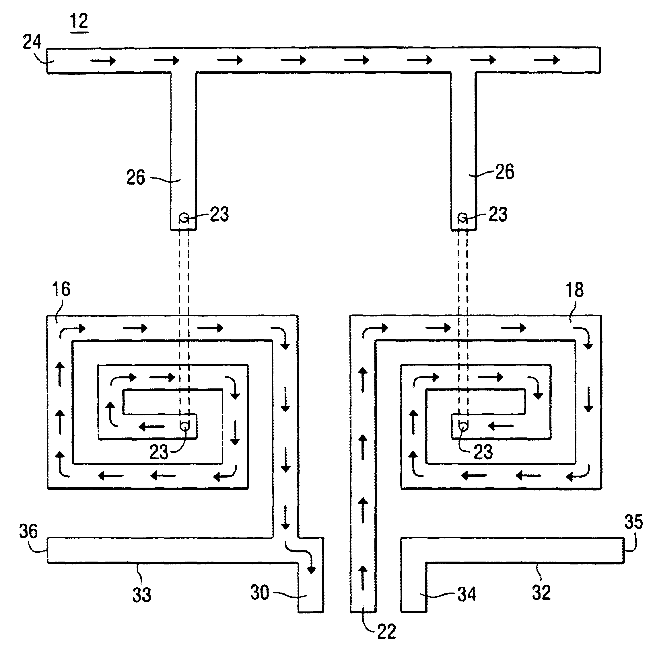
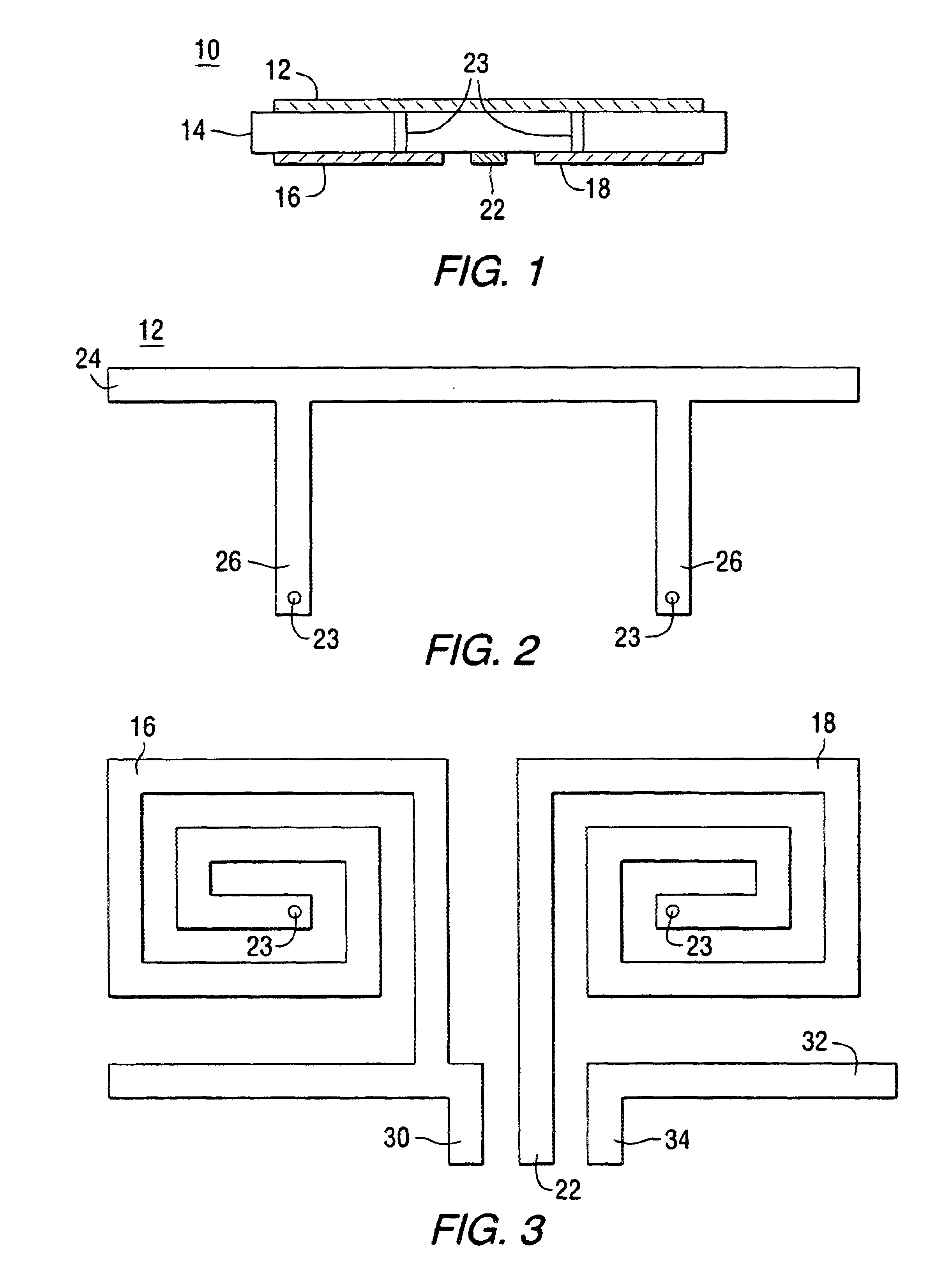
Before describing in detail the particular spiral antenna in accordance with the present invention, it should be observed that the present invention resides primarily in a novel combination of hardware elements related to an antenna. Accordingly, the hardware elements have been represented by conventional elements in the drawings, showing only those specific details that are pertinent to the present invention, so as not to obscure the disclosure with structural details that will be readily apparent to those skilled in the art having the benefit of the description herein.

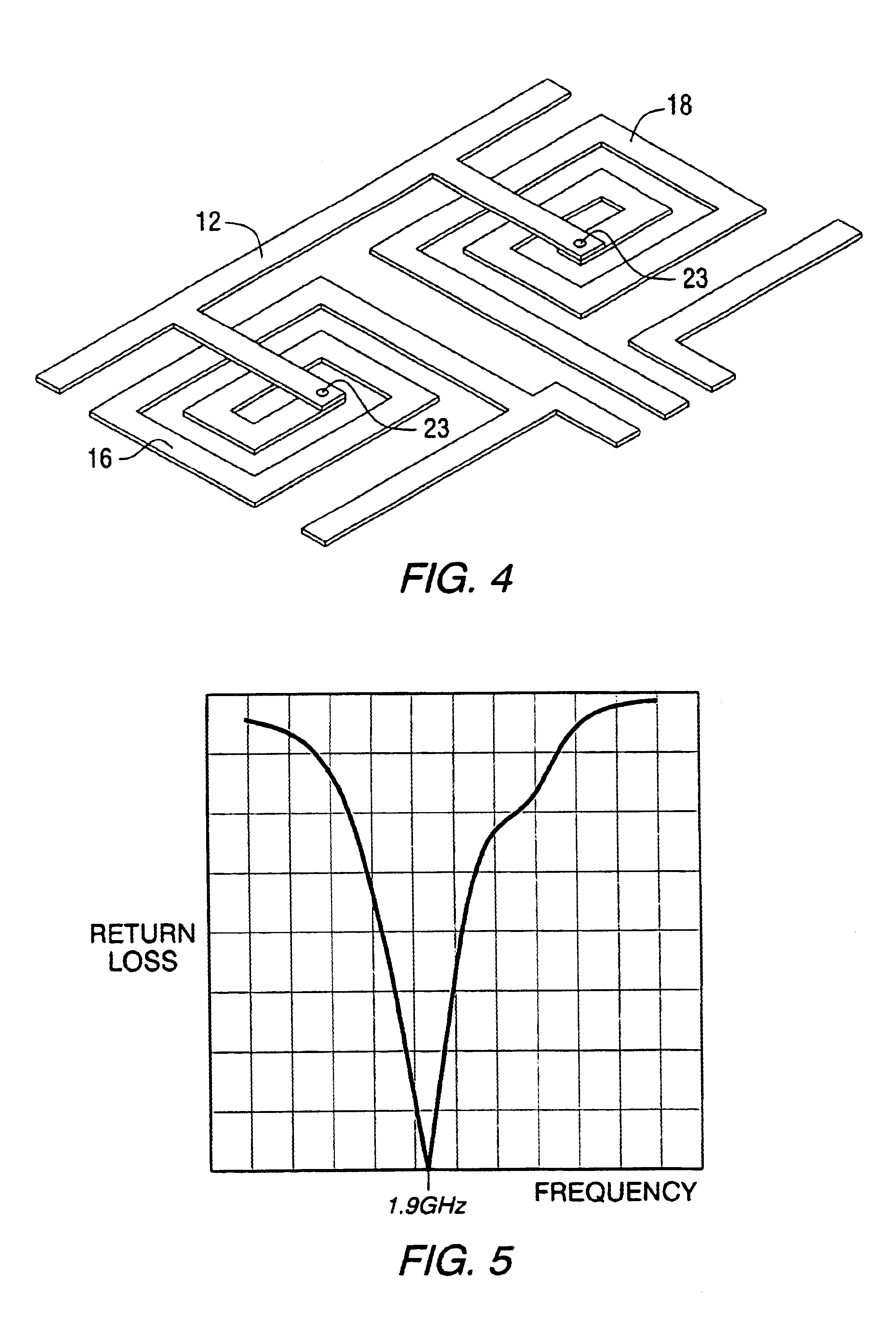
The antenna of the present invention is small enough to be installed within or in contact with the case of a wireless handset communications device. In one embodiment, the thickness of the antenna is less than about λ / 200 and the length and width less than about λ / 5. In one embodiment the antenna exhibits more than a 10% bandwidth at one or more resonant frequencies. This would generally be considered a relatively wi...


PUM


Abstract

An antenna incorporating slow wave structures. The antenna comprises at least two conductive serpentine structures disposed on a dielectric substrate and further comprising an oppositely disposed conductive top plate electrically connected to the conductive serpentine structures and farther electromagnetically connected thereto. In one embodiment the antenna further comprises a ground plane below the dielectric substrate.

Description

FIELD OF THE INVENTIONThe present invention relates generally to antennas for receiving and transmitting radio frequency signals, and more specifically to a low profile wideband antenna including at least two spiral elements.BACKGROUND OF THE INVENTIONIt is generally known that antenna performance is dependent on the antenna size, shape and the material composition of certain antenna elements, as well as the relationship between the wavelength of the received / transmitted signal and antenna physical parameters (that is, length for a linear antenna and diameter for a loop antenna). These relationships and physical parameters determine several antenna performance characteristics, including: input impedance, gain, directivity, polarization and radiation pattern. Generally, for an operable antenna, the minimum effective electrical length (which for certain antenna structures, for example antennas incorporating slow wave elements, may not be equivalent to the antenna physical length) must...

Claims


Application Information

Patent Timeline
Patent Type & Authority Patents(United States)
IPC IPC(8): H01Q1/38H01Q9/04H01Q1/24H01Q9/28H01Q9/27
CPCH01Q1/243H01Q9/285H01Q9/27H01Q1/38
Inventor JO, YOUNG-MINKIM, YOUNG-KIHAN, KYU-YOUNGSULLIVAN, SEAN F.KRALOVEC, JAY A.
Owner SKYCROSS INC
Why Eureka
Try Eureka