
Device for a quantified determination of the quality of surfaces

a technology of a measuring device and a surface, applied in the field of measuring devices and a method for determining the quality of surfaces, can solve the problems of large-scale size of many known measuring devices, large expenditure and expense in their acquisition and operation, and other known measuring devices being portable, and providing only insufficient precision or accuracy

Inactive Publication Date: 2005-01-11
BYK GARDNER
View PDF9 Cites 31 Cited by
  • Summary
  • Abstract
  • Description
  • Claims
  • Application Information

AI Technical Summary

Benefits of technology

[0018]The device according to the present invention has numerous advantages.
[0020]That the illuminating means in the inventive device has at least one light source rendered as an LED is of great advantage since at least one light source is then configured to be substantially resistant to aging.

Problems solved by technology

Many known measuring devices are however of large-scale size and represent great expenditure and expense in their acquiring and operating.
Other known measuring devices are portable, yet provide only insufficient precision or accuracy.

Method used


Image

  • Device for a quantified determination of the quality of surfaces
  • Device for a quantified determination of the quality of surfaces
  • Device for a quantified determination of the quality of surfaces

Examples


Embodiment Construction

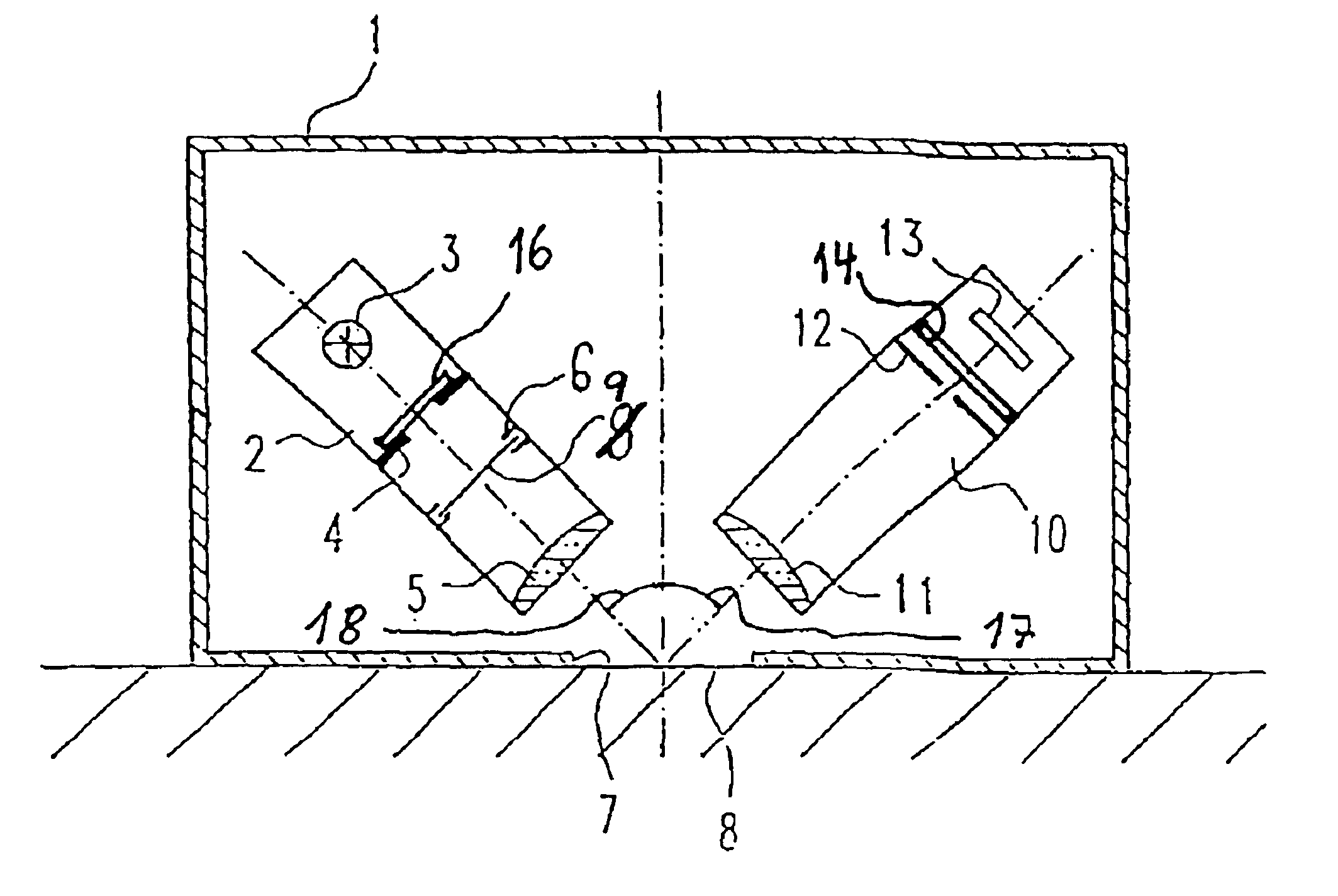
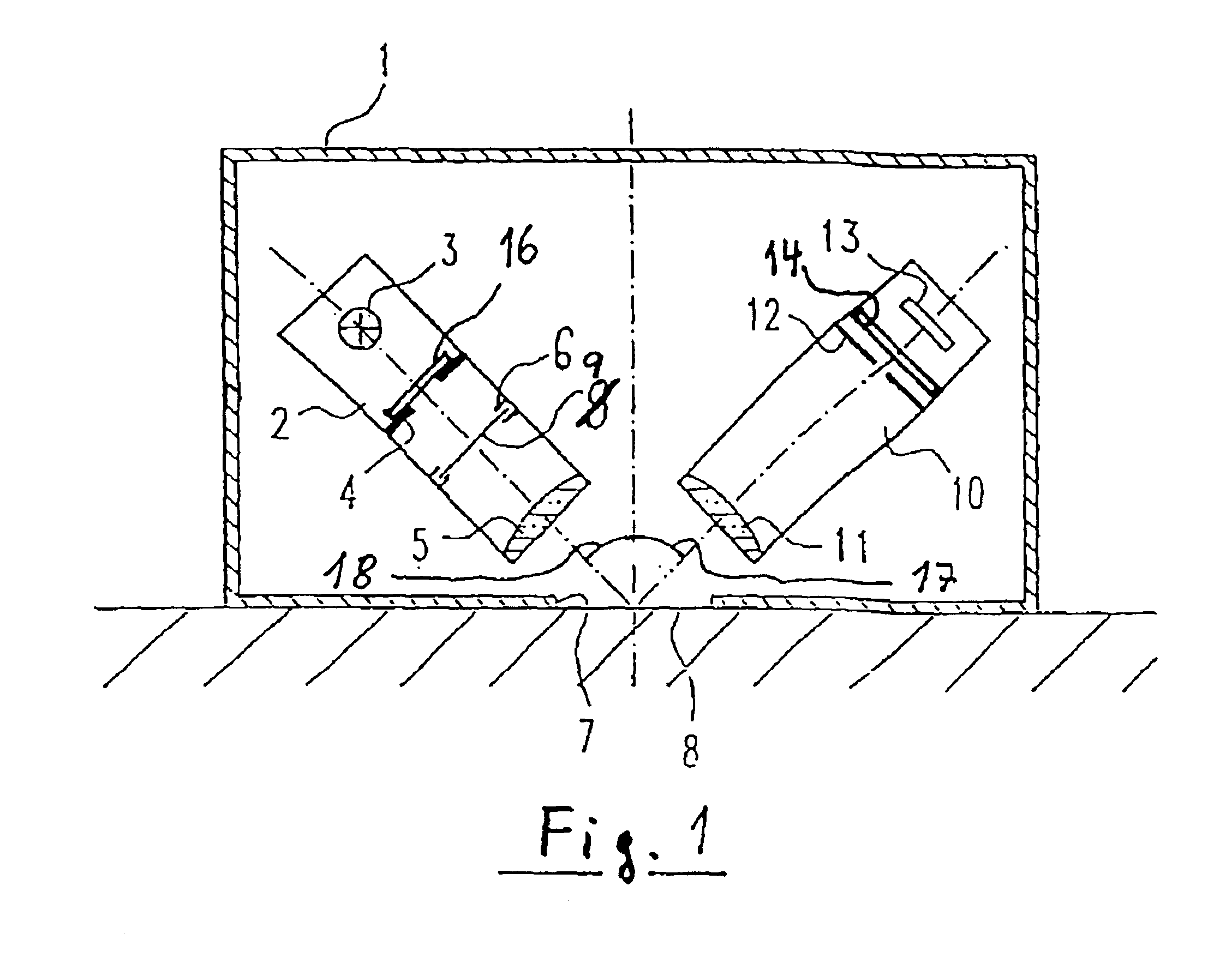
[0038]A first embodiment will now be described with reference to FIG. 1.

[0039]Measuring device 1 is provided with a housing which is placed upon the surface to examined, respectively measurement surface 8. A first optical means 2 comprises an illuminating means 3 of one or more light source(s) 3, the light thereof directed to said measurement surface at an angle 18 from the perpendicular to the measurement surface. Said first optical means furthermore comprises a scattering means having a diffusor retainer 4 and a diffusor 16, whereby said diffusor retainer 4 simultaneously serves as an aperture for the radiation emitted from light source(s) 3.

[0040]A filter means is arranged in the further downstream path of radiation from light source(s) 3 to the surface to be measured 8 which comprises a filter retainer 6 and a filter element 9, which influences the light emitted from light source 3 according to predetermined filter properties. A lens 5 in the first optical means parallelizes the...


PUM

PropertyMeasurementUnit
angleaaaaaaaaaa
circumferential angleaaaaaaaaaa
wavelengthaaaaaaaaaa

Abstract

The present invention relates to a device and a method for determining the quality of surface. An illuminating light source radiates light at a predetermined angle onto the measurement surface. An optical detecting device receives the light reflected from said measurement surface and converts same into an electrical measurement signal. A processor controls the measurement sequence and evaluates the measurement results, which are emitted via an output device. The illuminating light source comprises at least one light-emitting diode. The light emitted comprises at least blue, green and red spectral components in the visible range of the spectrum. A filter is provided in the path of radiation between the light source and the photosensor.

Description

BACKGROUND OF THE INVENTION[0002]The present invention relates to a device and a method for determining the quality of surfaces, respectively the visual properties of surfaces.[0003]The present invention relates in particular to a device and a method for the determining of the color and the color properties of surfaces.[0004]The quality, respectively the visual properties of a surface, is to be generally understood here as being those physical properties of a surface which determine the appearance of a surface for a human observer.[0005]Besides for color, respectively impression of color, these properties also include gloss, haze, distinctness of image (DOI), color brightness as well as surface texture and orange peel, etc.[0006]The color of a surface is an especially important criterion for the assessing of surface quality, because the color, respectively impression of color, is a decisive feature for the overall impression of a product in the case of numerous consumer and technica...

Claims


Application Information

Patent Timeline
Patent Type & Authority Patents(United States)
IPC IPC(8): G01N21/57G01N21/25G01N21/55G01J3/51G01J3/00G01J3/50G01J3/10G01N21/01G01N21/27G01N21/64G01N21/95
CPCG01J3/02G01J3/027G01J3/0272G01J3/0286G01J3/10G01N21/57G01J3/501G01J3/502G01J3/51G01N21/251G01J3/50
Inventor SCHWARZ, PETER
Owner BYK GARDNER
Learn More