System and method for measuring an optical path difference in a sensing interferometer

a technology of optical path difference and sensing interferometer, which is applied in the field of optical measuring instruments, can solve the problems of inconvenient measurement, inability to tell if the mirror is moving in one direction, and interference on the detector, and achieve the effect of more robust and reliable measurements

Active Publication Date: 2005-01-11
FISO TECH
View PDF13 Cites 69 Cited by
  • Summary
  • Abstract
  • Description
  • Claims
  • Application Information

AI Technical Summary

Benefits of technology

The addition of a third light source, according to the present invention, can be used to further compensa

Problems solved by technology

The two beams then recombine and the resulting interference is incident on the detector.
However, simple and elegant this method might appear, it suffers from several handicaps.
First, one cannot tell if the mirror is moving in one direction or the other.
Also, alignment variations or intensity variations of the source can severely affect the displacement reading, as these variations can be interpreted as a legitimate pulse.
Althoug

Method used


Image

  • System and method for measuring an optical path difference in a sensing interferometer
  • System and method for measuring an optical path difference in a sensing interferometer
  • System and method for measuring an optical path difference in a sensing interferometer

Examples


Embodiment Construction

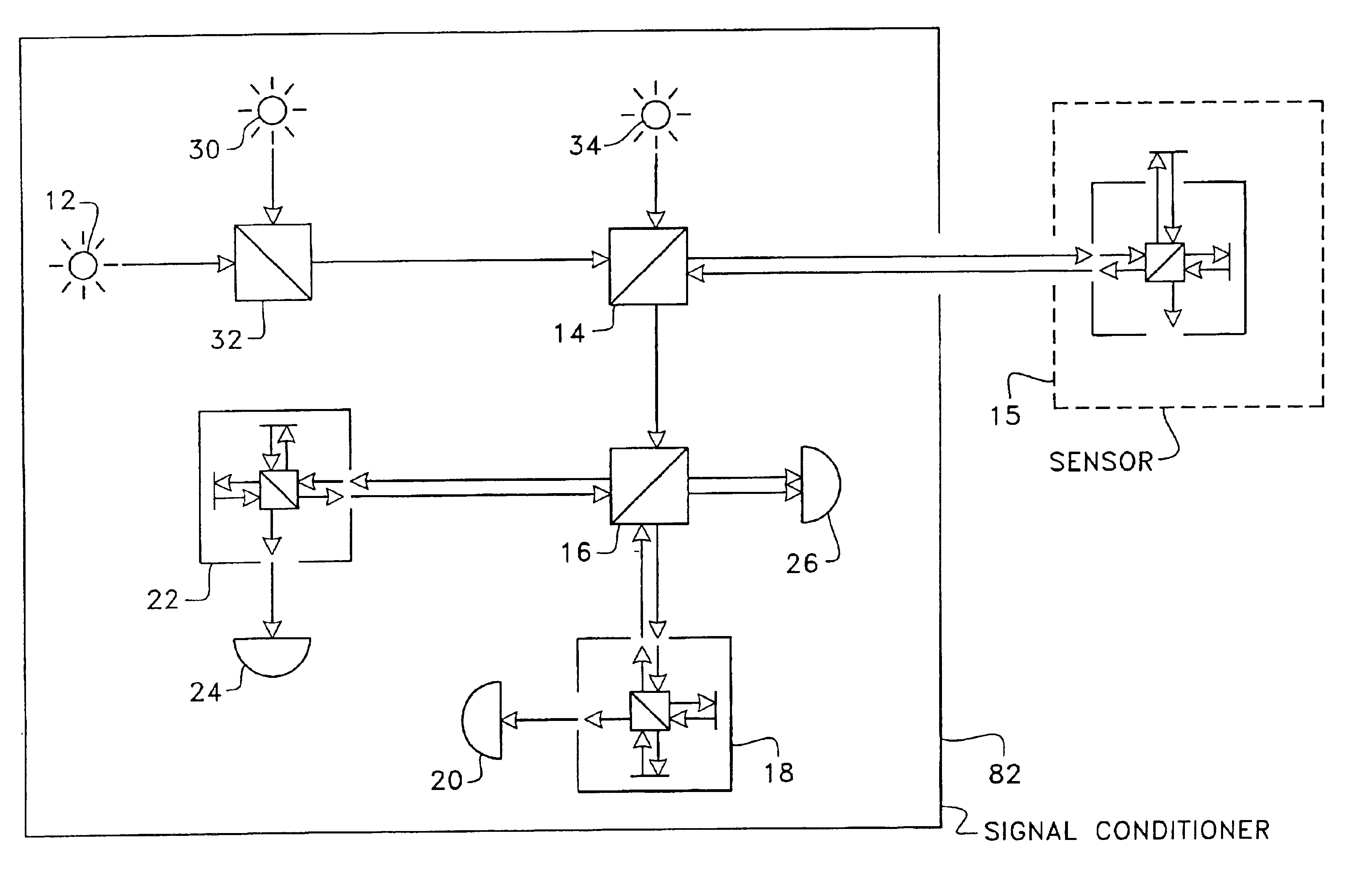
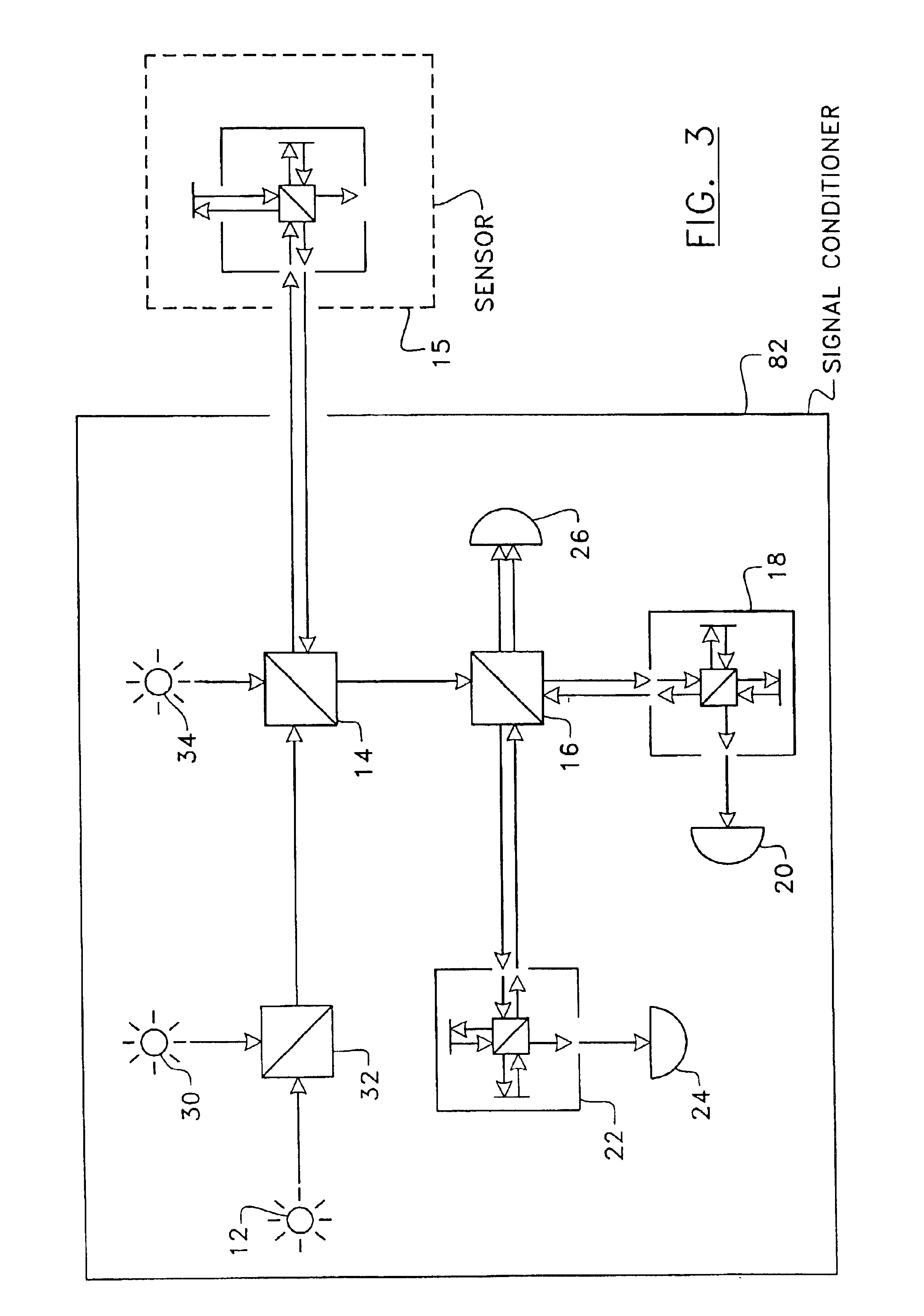
Referring to FIG. 3, there is shown an embodiment of the system according to the present invention. A limited version of the system may comprise a single light source 12 preferably having a large spectrum (such as an electro luminescent diode). Light generated by the light source 12 goes through a first beam splitter 14 and is directed to a remote sensing interferometer 15. The sensing interferometer 15 (or sensor) is here represented as a Michelson-type but it could be any type of two-arm interferometer, such as a low-finesse Fabry-Perot. The reflected light from the sensing interferometer 15, which encodes in its spectrum all the information one needs to measure its optical path difference (OPD), then goes back to the first beam splitter 14 and is directed to a second beam splitter 16. There, the light signal is split in two beams. A first beam goes through a first reference interferometer 18. The intensity of the light transmitted by the interferometer 18 is measured by a photo d...


PUM


Abstract

An apparatus and a method of measuring an optical path difference in a sensing interferometer. Light from a source is directed in the sensing interferometer. The light reflected from the sensing interferometer is splitted into first and second beams respectively directed into two reference interferometers having optical path differences greater than the coherence length of the source and such that the optical signals are in quadrature. The intensities of the light transmitted by the reference interferometers and recombined light reflected from the reference interferometers are detected for measuring the optical path difference in the sensing interferometer. Additional light sources allow for correction of internal perturbations and absolute measurement of the optical path difference in the sensing interferometer.

Description

FIELD OF THE INVENTIONThe present invention relates to optical measuring instruments, and more particularly to a system and a method for measuring an optical path difference in a sensing interferometer used for example to sense a pressure, a temperature, a displacement, a stretching, a magnetic field, an electric current, etc.BACKGROUNDThe spectral response of a two-arm optical interferometer is a periodic function having a sinusoidal shape. The period of this function is inversely proportional to the difference in length between the two arms of the interferometer. This difference is called the optical path difference (OPD). Any perturbation on the length of any or both arms, whether by geometrical deformation of the interferometer or by perturbation in the optical path traveled by the light will change the period of the spectral response.This property of optical interferometers to encode their OPD in the spectrum (or phase) of light is well known in the art and is often used to det...

Claims


Application Information

Patent Timeline
IPC IPC(8): G01B9/02
CPCG01B9/02012G01B9/02007G01B9/0209G01B9/02081G01B9/02023G01B2290/45G01B2290/25
Inventor VAN NESTE, RICHARDBELLEVILLE, CLAUDEPRONOVOST, DANIELPROULX, ALAIN
Owner FISO TECH
Why Eureka
Try Eureka