Method and apparatus for measurement of concentration of a specific analyte in a biological material

a technology of biological material and concentration, applied in the direction of instruments, measuring devices, transmissivity measurements, etc., can solve the problems of difficult to obtain adequate calibration, cumbersome and expensive methods, limited practical use, etc., and achieve robust and reliable measurement, large structural features, and robustness.

Active Publication Date: 2017-03-07
MANTEX IP AB
View PDF14 Cites 2 Cited by
  • Summary
  • Abstract
  • Description
  • Claims
  • Application Information

AI Technical Summary

Benefits of technology

[0018]The present invention is based on the understanding that the Beer-Lambert law may be used to determine the concentration of a specific analyte. The Beer-Lambert law states that A=log(I / I0)=εcd where A is the absorbance of the sample at a certain wavelength, ε, is the absorptivity or extinction coefficient, c is the concentration of the sample and d is the path length of radiation / energy through the sample. From this follows that A*1 / εc=d, which means that A is proportional to d, and plotting of A against d forms a linear regression line with a slope 1 / εc. The present invention provides a very efficient and robust way of determining pairs of A and d values, enabling a reliable and robust measurement of the concentration c.
[0050]Preferably, the length difference between the shortest path and the longest path of the at least two paths used for the measurement is at least 20 mm, and even more preferred at least 30 mm, and most preferably at least 50 mm. This enables a very robust and reliable measurement.

Problems solved by technology

The complex set-up and interaction with the sample material to be measured makes this method cumbersome and expensive, and also provides limited practical use since the described method can only be used for certain types of liquid solutions.
Further, it is also difficult to obtain adequate calibration.

Method used


Image

  • Method and apparatus for measurement of concentration of a specific analyte in a biological material
  • Method and apparatus for measurement of concentration of a specific analyte in a biological material

Examples


Embodiment Construction

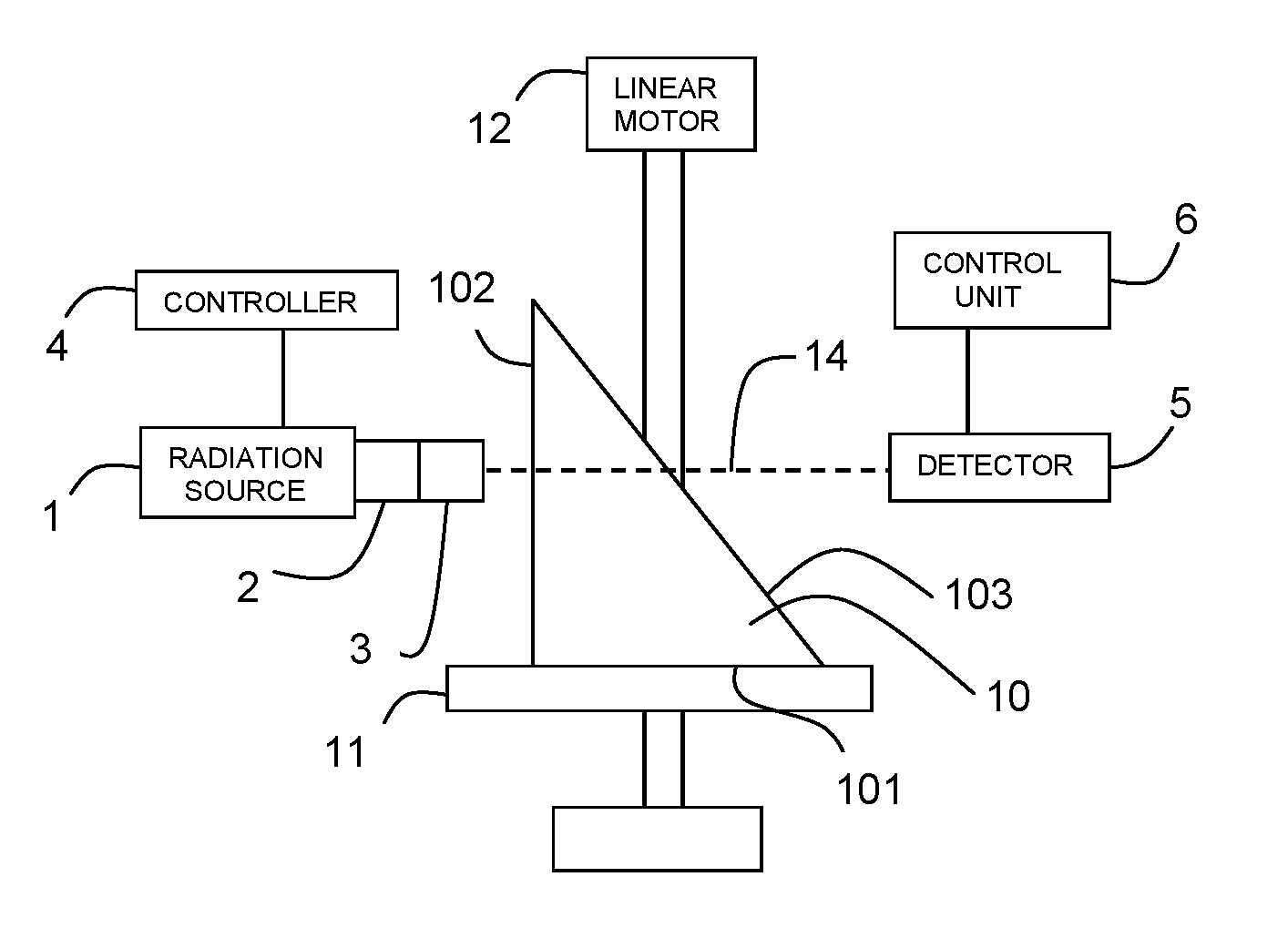
[0056]Referring to FIG. 1, an exemplary measurement apparatus according to the present invention comprises a radiation source 1 for providing radiation of one or several energy level(s) / wavelength(s). Preferably, the radiation source is an X-ray tube for provision of X-ray radiation of two or more different wavelengths. Preferably, the X-ray tube operates in the range 20-150 kVp. The output radiation from the radiation source 1 is preferably directed towards a target area through a collimator 2 and a lens 3. The radiation source 1 is controlled by means of a controller 4.

[0057]On the opposite side of the target area, a detector 5 is arranged to receive radiation transmitted through material arranged in the target area. The detector 5 comprises any mechanism capable of converting energy from detected radiation into signals that may be processed by the apparatus. The detector 5 is preferably a semiconductor detector, comprising an array of semiconductor detector areas. Detector(s) is / ...


PUM

PropertyMeasurementUnit
lengthaaaaaaaaaa
path lengthaaaaaaaaaa
path lengthsaaaaaaaaaa

Abstract

A method and apparatus for determining the concentration of a specific analyte in a sample of biological material are disclosed. The sample is placed in a sample container (10) which provides at least two radiation paths (14) with different lengths through the sample container (10), and is sequentially irradiated with electromagnetic radiation, e.g. X-rays. The amount of radiation penetrating the sample is detected, and absorbance is determined based on the detected radiation. During irradiation, the sample container (10) is moved in relation to the radiation source (1) and detector (5) so that absorbance measurements at different path-lengths are acquired. A regression line from the absorbance values and path lengths is determined, such that a slope of the regression line is obtained, and based on this slope, the concentration of the specific analyte is determined.

Description

TECHNICAL FIELD OF THE INVENTION[0001]The present invention relates to a method and an apparatus for determining the concentration of a specific analyte in a sample of biological material.BACKGROUND[0002]Spectroscopic or spectrometric analysis is a broad field in which the composition and properties of an analyte in any phase, viz, gas, liquid, solid, are determined from the residual electromagnetic spectra arising from the interaction (eg. absorption, luminescence, or emission) of the analyte and energy. One aspect of chemical analysis, known as absorptiometry, involves interaction of radiant energy with the analyte of interest. One such method is known as absorption photometry, in which the optical absorption of samples are measured. The absorption is the amount of energy absorbed by the sample. In a simple spectrophotometer the studied sample material is placed in a container, also known as a cuvette or sample cell. Electromagnetic radiation (light) of a known wavelength, λ, (i.e...

Claims


Application Information

Patent Timeline
Patent Type & Authority Patents(United States)
IPC IPC(8): G01N23/06G01N21/59G01N23/08G01N23/083G01N23/087G01N23/10G01N21/03
CPCG01N23/10G01N21/0303G01N21/5911G01N23/06G01N23/08G01N23/083G01N23/087G01N2223/32G01N2223/619
Inventor KULLENBERG, RAGNARTORGRIP, RALFDANIELSSON, FREDRIKLANDSTROM, ERIC
Owner MANTEX IP AB
Why Eureka
Try Eureka