Gear tooth and thread grinding machine

a technology of gear teeth and grinding machines, which is applied in the direction of gear teeth, worms, belts/chains/gears, etc., can solve the problems of gear machined, and unable to meet the requirements of chipforming

Inactive Publication Date: 2005-01-18
REISHAUER
View PDF16 Cites 11 Cited by
  • Summary
  • Abstract
  • Description
  • Claims
  • Application Information

AI Technical Summary

Benefits of technology

It is an object of the present invention to provide a machine for chip-forming machining, in particular a grinding machine, on which both gears a

Problems solved by technology

The limits lie on the one hand in the machinery costs, which increase with the degree of outfitting, i.e. the number of machining units, NC axes etc., and on the other hand in the time expenditure for setting the machining process.
The setting work is chiefly a substantial expense factor in the case of machining medium sized and small series, where the machine is re

Method used


Image

  • Gear tooth and thread grinding machine
  • Gear tooth and thread grinding machine
  • Gear tooth and thread grinding machine

Examples


Embodiment Construction

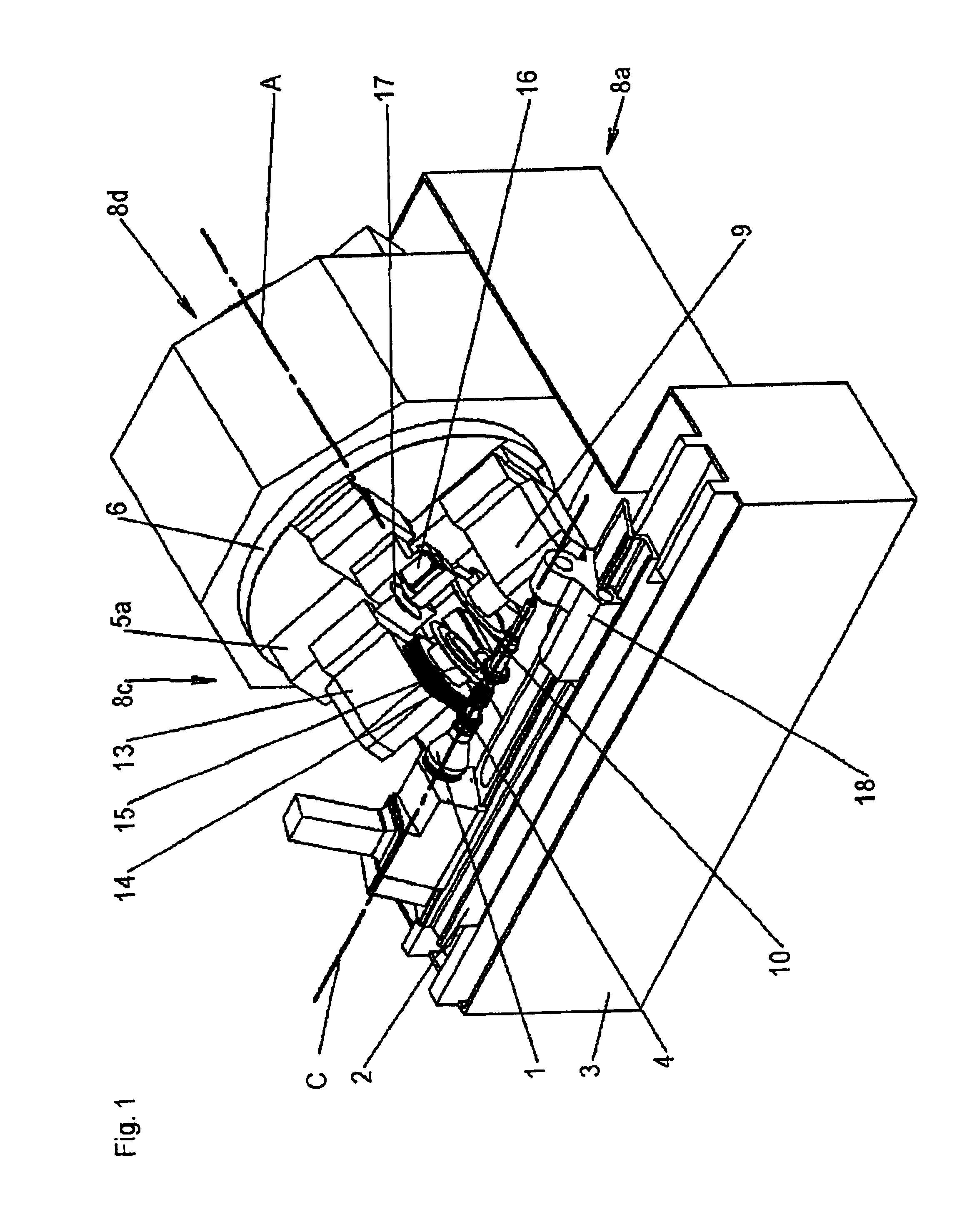
FIG. 1 depicts the view of a gear tooth and thread grinding machine from the operater side. A work spindle 1 for the accommodation of a workpiece 4 to be machined is located for rotation about a first axis C′ on a work slide 2. The work slide 2 is located on a machine bed 3 in guideways for displacement parallel to rotary axis 2. Located in the section of the machine bed 3 opposite the work spindle 1 is a swivel head 6, which is swivellable about an axis A, preferably at right angles to axis C′ and horizontal.

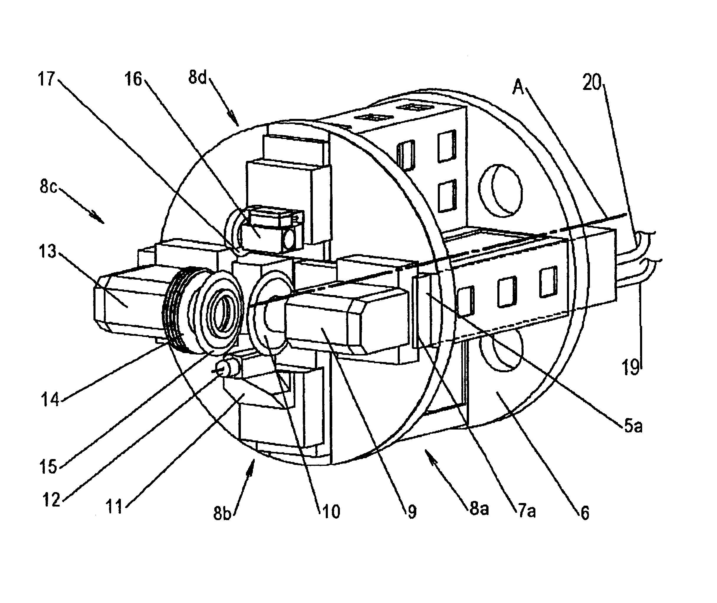
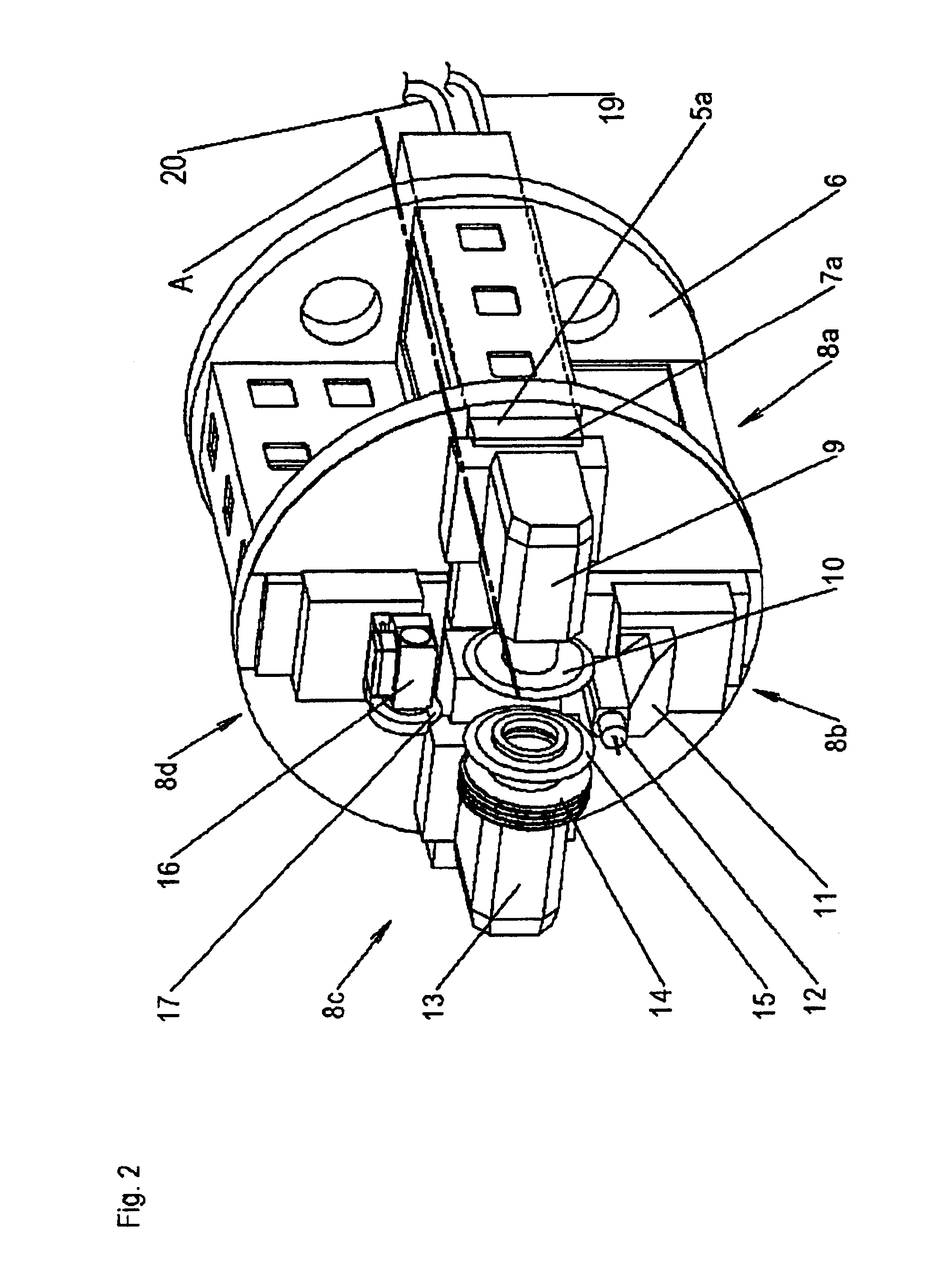
Arranged according to the invention on the front end face of the swivel head 6 directed towards the work spindle 1 are at least two—preferably up to four—functional units 8a, 8b, 8c, 8d. Depending on the intended application of the machine these functional units 8a, 8b, 8c, 8d are equipped with like or unlike machining tools 10, 14, 15, 17 or measuring tools 12. The functional units 8a, 8b, 8c, 8d can be arranged directly on the swivel head 6. It is an advantage, however, to ar...


PUM

PropertyMeasurementUnit
Timeaaaaaaaaaa
Angleaaaaaaaaaa
Angleaaaaaaaaaa

Abstract

The invention concerns a machine for the chip-forming machining and the measurement of gears and screw-type workpieces. Arranged on a swivel head (6) swivellable about an axis (A) at right angles to the rotary axis of the workpiece (4) are functional units (8a, 8b, 8c, 8d) with machining and measuring tools (10, 12, 14, 15, 17) which are displaceable radially and parallel relative to the swivel axis (A), which said tools can be brought consecutively into engagement with the workpiece (4), thus making possible the application of different tools (10, 12, 14, 15, 17) and machining techniques in the same work set-up without colliding. The work spindle (1) is driven by electric motor either directly or via a gear unit.

Description

FIELD OF THE INVENTIONThe invention concerns a machine for chip-forming machining. It serves for the grinding and measuring of gears and screw-type workpieces such as, for example, leadscrews, thread rolling dies and screw compressor screws.BACKGROUND OF THE INVENTIONOne of the widespread, proven principles for increasing the economic efficiency of the chip-forming machining of workpieces is the consecutive performance of various machining operations in a single work set-up. Examples of this are, amongst others, automatic lathes and production centers. With a number of different cutting tools on one or several different machining units, all workpiece outer surfaces are machined that are accessible for machining in the relevant work set-up. Measuring operations on the workpiece surface are also included in the automatic process sequence. A multifunctional production center can substitute for a number of machines with different functions and machining techniques such as turning, milli...

Claims


Application Information

Patent Timeline
IPC IPC(8): B23F17/00B23Q1/25B23Q1/52B23Q39/00B23F23/00B23F23/12B23F5/00B23F5/02B23Q39/02B24B27/00B24B5/00B24B41/00B24B5/36B24B41/04B23G1/36
CPCB23F5/02B23F23/1218B23F23/1225B23Q1/52B23Q39/02B24B5/36B24B27/0061B24B41/04B23F17/006Y10T29/5168B23Q2039/004Y10T82/2508Y10T29/517Y10T409/300672Y10T29/511Y10T29/5176Y10T409/10
Inventor RONNEBERGER, ERICH
Owner REISHAUER
Why Eureka
Try Eureka