Load bearing fabric attachment and associated method

Inactive Publication Date: 2005-01-18
JSJ SEATING +1
View PDF63 Cites 33 Cited by
  • Summary
  • Abstract
  • Description
  • Claims
  • Application Information

AI Technical Summary

Benefits of technology

The present invention provides a simple and effective method for attaching a load bearing fabric to a support structure. Because the outer ring and inner ring are configured to stretch the fabric upon assembly of the two components, the fabric need not be stretched prior to molding or prior to attachment to the outer ring. Further, the amount of stretch is engineered into the inner and outer rings, and need not

Problems solved by technology

One particularly important challenge related to the use of load bearing fabric is the challenge of attaching the fabric to the support structure.
This task is particularly challenging because it is typically important to attach the fabric to the support structure in a stretched or tensioned state.
Conventional attachment methods often fail to provide the necessary strength and durability to withstand the forces applied to the fabric.
In some applications, the bond itself may fail and in other applications, the method of attachment may cause the fabric to unravel or separate along the periphery of the fabric.
In such applications, the challenge is to secure the outer ri

Method used


Image

  • Load bearing fabric attachment and associated method
  • Load bearing fabric attachment and associated method
  • Load bearing fabric attachment and associated method

Examples


Embodiment Construction

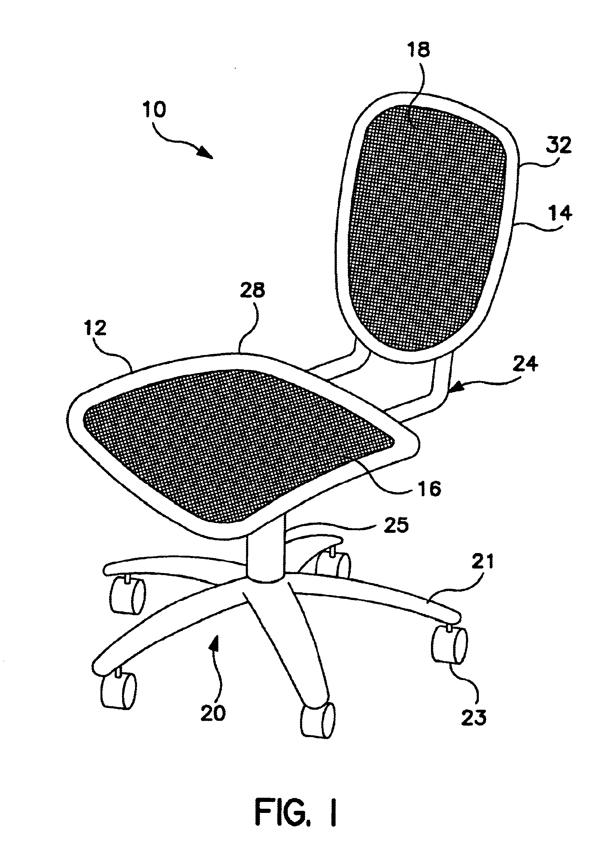
For purposes of disclosure, and not limitation, the present invention is described in connection with an office chair 10 having load bearing fabric that forms the seat and back of the chair. The present invention is well suited for use in a wide variety of other applications incorporating load bearing fabric. For example, the present invention is well suited for use with footwear soles, mattresses, cots, wheelchairs and a variety of seating applications outside of office furniture.

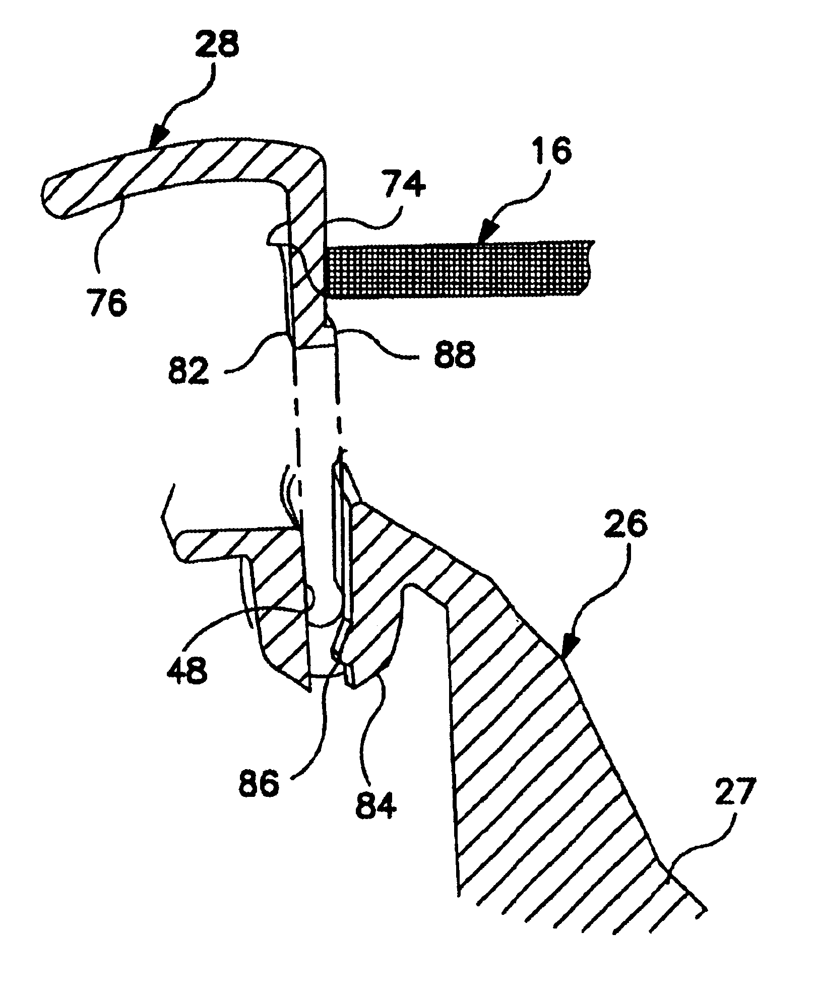
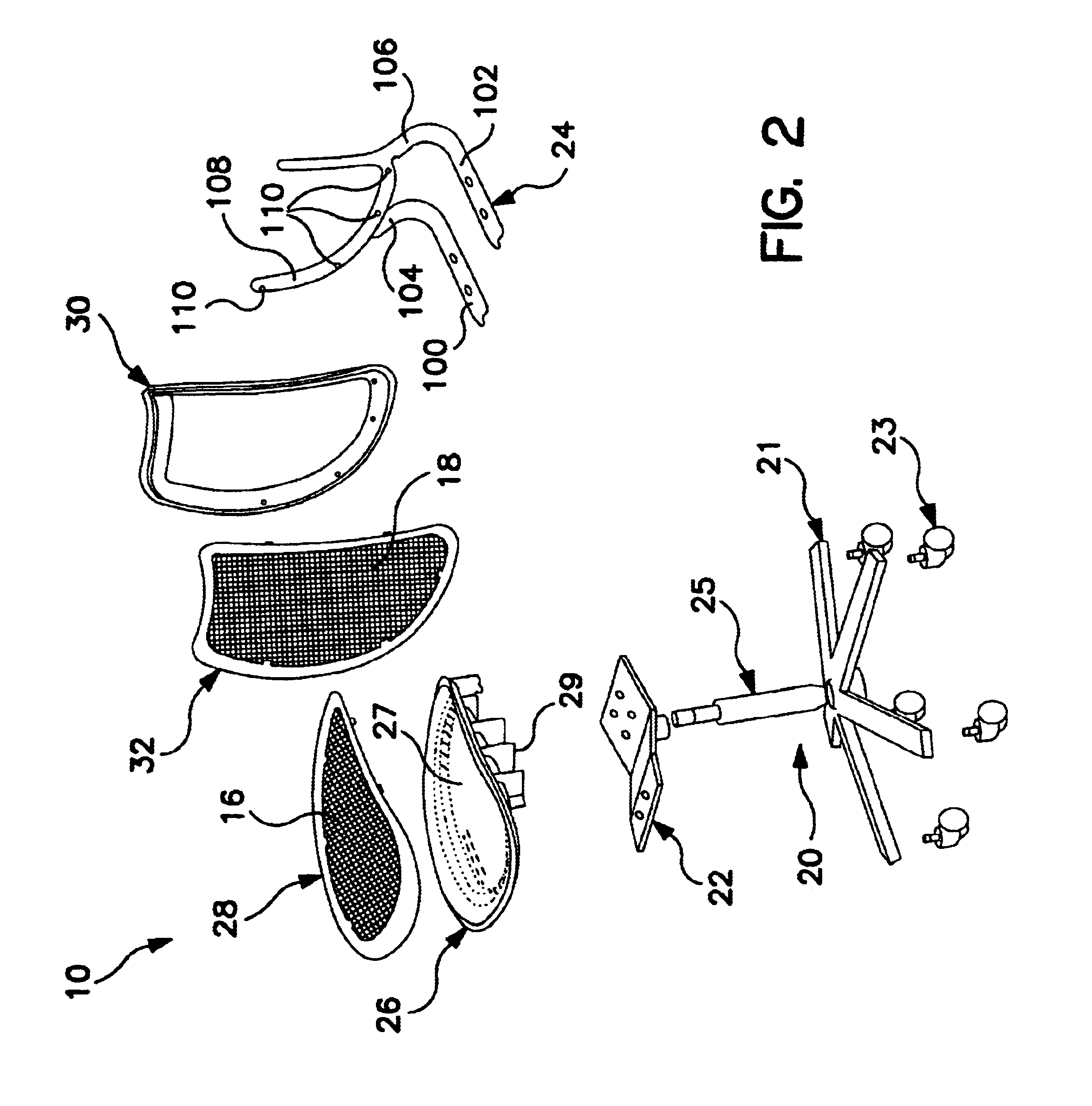
An office chair manufactured in accordance with a preferred embodiment of the present invention is shown in FIG. 1, and generally designated 10. Referring also to FIG. 2, the office chair 10 includes a conventional base 20 upon which is supported a seat 12 and a back 14. The seat 12 and back 14 each include a load bearing fabric 16 and 18, respectively, that forms the corresponding support surface. The seat 12 includes an inner ring 26 that is preferably an integral portion of the seat frame and an outer r...


PUM

PropertyMeasurementUnit
Forceaaaaaaaaaa
Structureaaaaaaaaaa
Tensionaaaaaaaaaa

Abstract

An attachment structure for a load bearing fabric. The attachment structure includes interfitted inner and outer rings. The outer ring includes a fabric leg 74 carrying a load bearing fabric. The inner ring defines a channel receiving the fabric leg 74. The inner ring and outer ring are configured to stretch the fabric upon insertion of the fabric leg 74 into the channel. The present invention also provides a method for securing a load bearing fabric to a support structure, generally including the steps of (a) providing an outer ring having fabric leg 74, (b) attaching a section of load bearing fabric to the fabric leg 74, (c) providing an inner ring having a channel adapted to receive the leg of the outer ring and (d) installing the outer ring to the inner ring by inserting the leg into the channel, the insertion forcing the fabric down into the channel and stretching the fabric to the desired tension.

Description

BACKGROUND OF THE INVENTIONThe present invention relates to load bearing fabric, and more particularly to components and methods for securing a load bearing fabric to a support structure.The use of load bearing fabrics continues to grow dramatically in various industries, including the automotive, office and home seating industries. The term “load bearing fabric” is commonly used to refer to a class of high strength, highly durable textiles that are typically woven from elastomeric monofilaments and conventional yarns. Some of today's load bearing fabrics have greater strength and durability characteristics than spring steel and other conventional load bearing materials. In addition to their strength and durability characteristics, load bearing fabrics are lightweight and typically have a high modulus of elasticity. Therefore, they are well-suited for use in a variety of applications where a strong and durable yet lightweight or elastic load bearing surface is desired, for example, ...

Claims


Application Information

Patent Timeline
IPC IPC(8): A47C7/46A47C1/031A47C1/03A47C1/022A47C1/032A47C31/02B29C45/14B68G7/05
CPCA47C7/282A47C21/022B29C45/14065B29C45/14336B29C45/14418A47C31/023A47C7/462Y10T29/486B29K2713/00B29L2031/443Y10T428/24008Y10T29/49869Y10T29/49867Y10T29/49872Y10T428/24777
Inventor COFFIELD, TIMOTHY P.WATSON, RONNIE K.PETERSEN, SOREN S. INGOMARCHROSTOWSKI, MATTHEW E.LEWIS, RANDALL CLARK
Owner JSJ SEATING
Why Eureka
Try Eureka