Gas sensor arrangement

a technology of gas sensors and sensors, applied in the direction of material thermal analysis, material analysis using sonic/ultrasonic/infrasonic waves, material analysis using microwave means, etc., can solve the problems of increasing the service life of the sensor, and increasing the cost of gas sensors

Inactive Publication Date: 2005-01-18
GASBEETLE
View PDF12 Cites 41 Cited by
  • Summary
  • Abstract
  • Description
  • Claims
  • Application Information

AI Technical Summary

Benefits of technology

A further advantage of a gas sensor having more than two sources lies in the considerable breakdown safety, that is if a measuring source fails, the sensor will continue to operate using the additional source. The preferred embodiment in this case is a gas sensor having 3 radiation sources, a measuring source, a reference source, an additional measuring or additional reference source. The service life of the sensor may thus be extended many times. In addition, minimum aging of the reference radiation source may be compensated by the further radiation so

Problems solved by technology

This calibration usually has to be carried out by trained personnel and is thus very cost-intensive.
Since the detectors represent a main cost factor of the gas sensors and since double signal processing is required, such gas sensors are relatively expensive.
In addition, different drift for the detectors may occur during

Method used


Image

  • Gas sensor arrangement
  • Gas sensor arrangement
  • Gas sensor arrangement

Examples


Embodiment Construction

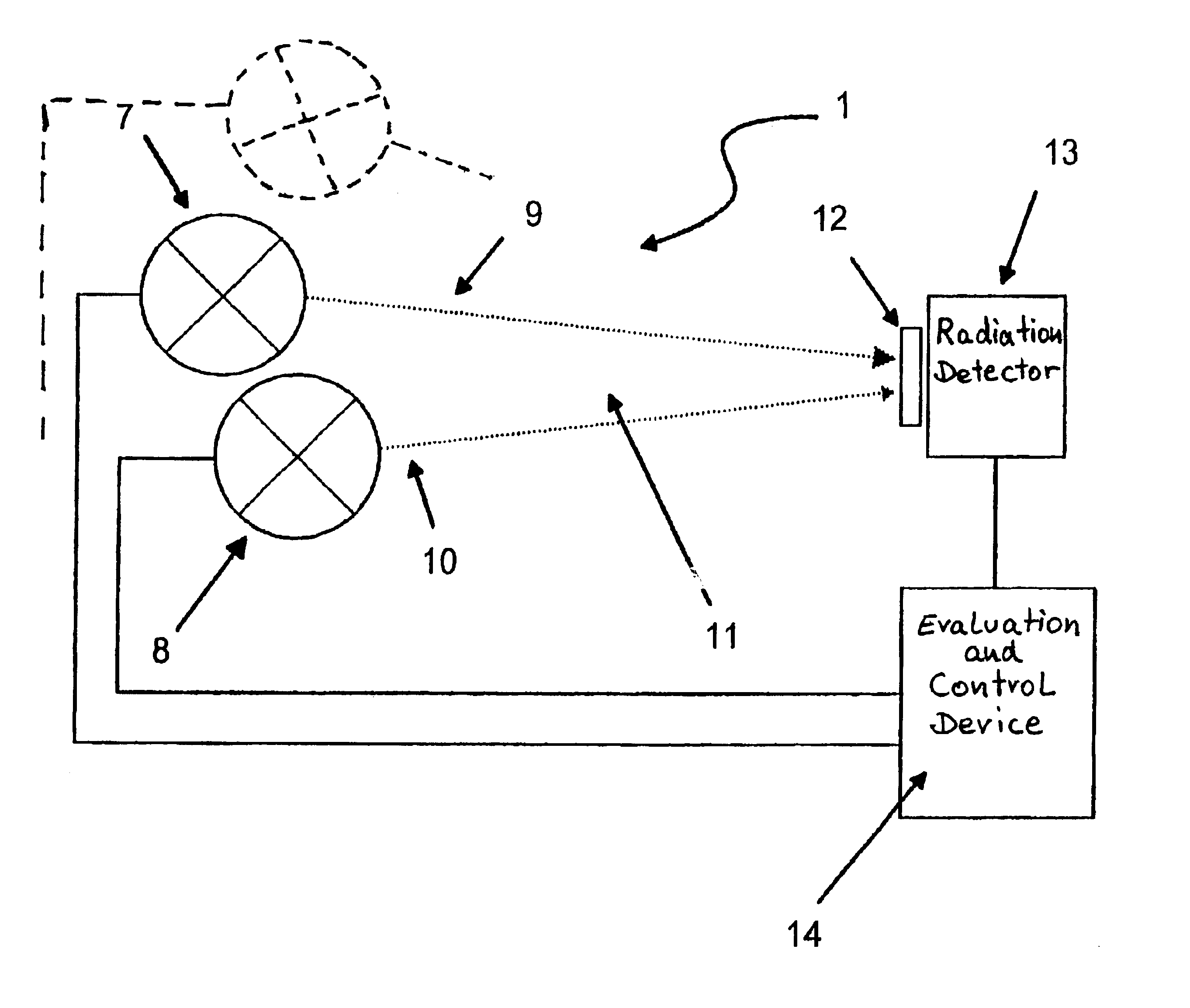
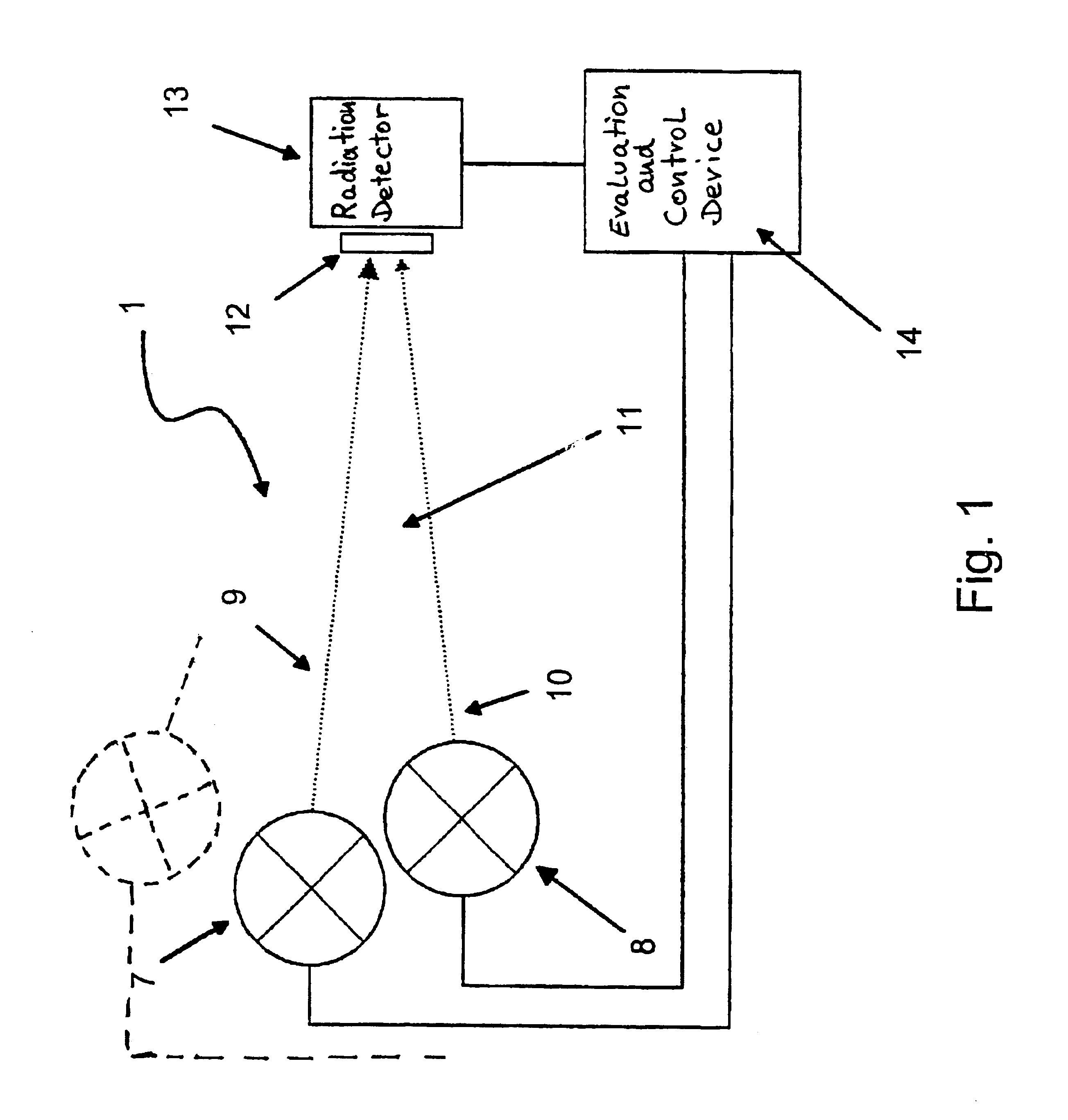
The gas sensor arrangement according to FIG. 1 is designed as an infrared gas sensor arrangement and has an infrared gas sensor 1 structured conventionally as one unit, which infrared gas sensor 1 is connected to an evaluation and control device 14, for example by means of a plug arrangement.

In the schematic structure of the infrared gas sensor 1 according to FIG. 1, a measuring radiation source is designated by the reference number 7 and a reference radiation source is designated by the reference number 8. The radiation sources 7, 8 preferably have identical parameters and radiate with a broadband radiation spectrum. In gas sensor operation, the measuring radiation source 7 is used for measuring the measuring gas concentration, it may be operated continuously or in pulsed-mode operation for this. On the other hand, the reference radiation source 8 is only switched on at considerable temporal intervals to determine aging of the measuring radiation source 7. The radiation sources 7, ...


PUM


Abstract

A gas sensor configuration comprises a radiation-emitting radiation device, a gas measuring chamber, a detector unit and an evaluation device. A measuring gas that contains at least one gas component is present in the gas measuring chamber. The evaluation device detects the gas component and/or its concentration depending on the output signal of the detector unit. The radiation emitting device comprises at least one source that emits a measuring radiation and at least one reference radiation source, the latter being switched on periodically to measure the aging state of the source that emits the measuring radiation. The evaluation device detects the aging of the source that emits the measuring radiation on the basis of deviations with respect to the output signals of the detector unit when the reference radiation source and the source that emits the measuring radiation are switched on, and, if necessary, compensates for the aging.

Description

FIELD OF THE INVENTIONThe invention relates to a gas sensor arrangement having a radiation device emitting radiation, a gas measuring chamber, a detector device and an evaluation device, wherein a measuring gas containing at least one gas component is situated in the gas measuring chamber and the evaluation device determines the gas component and / or its concentration depending on the output signal of the detector device.BACKGROUND OF THE RELATED TECHNOLOGYIt is known that many gases absorb radiation particularly in the infrared wavelength range, wherein this absorption occurs at a wavelength which is characteristic for the gas in question, for example for CO2 at 4.24 μm. With the aid of infrared gas sensors it is thus possible to establish the presence of a gas component or the concentration of a gas component.Known infrared gas sensors have, for example a broadband radiation source, an absorption path or a measuring chamber, a wavelength-selective element, for example an interferen...

Claims


Application Information

Patent Timeline
IPC IPC(8): G01N21/31G01N21/35G01N29/00G01N21/00G01N21/27G01N21/3504G01N21/37G01N21/61
CPCG01N21/1702G01N21/3504G01N21/274G01N2021/1704
Inventor SHULGA, ALEKSANDRSCHMALE, UDOMULLER, HOLGER
Owner GASBEETLE
Why Eureka
Try Eureka