System and method for enhanced telescoping engagement

a technology of telescoping and engagement, applied in the direction of rod connection, variable height table, machine support, etc., can solve the problems of conventional telescoping assembly not being able to support a significant load or weight, conventional telescoping assembly is relatively expensive and time-consuming to manufacture, and the use of telescoping assemblies has traditionally been limited

Inactive Publication Date: 2005-01-18
LIFETIME PRODUCTS
View PDF24 Cites 62 Cited by
  • Summary
  • Abstract
  • Description
  • Claims
  • Application Information

AI Technical Summary

Benefits of technology

A need therefore exists for a telescoping assembly that eliminates the above-described disadvantages and problems.

Problems solved by technology

Although there are many applications in which a telescoping assembly may beneficially be incorporated, the use of telescoping assemblies has traditionally been limited because of manufacturing and cost considerations.
Finally, conventional telescoping assemblies are not able to support a significant load or weight because the weight causes the telescoping assembly to retract into the storage position.
Conventional telescoping assemblies are relatively expensive and time consuming to manufacture because, inter alia, of the strict tolerances required for the inner and outer diameters of each of the telescoping members.
In particular, if the clearance or space between adjacent telescoping members is too large, the telescoping members may not stay aligned along the same axis and the members may undesirably move or “wobble.” That is, the telescoping members do not remain coaxial and there is excessive amount of motion or “slop” between the telescoping members.
This undesired movement or slop causes the telescoping assembly to appear somewhat rickety and unstable, and often creates an impression of poor workmanship and quality in the mind of the consumer or user.
This undesired movement may also cause the device to be unstable, unbalanced and, in some situations, unusable.
On the other hand, if clearance between adjacent telescoping members is too small, the parts may not fit together or the telescoping members may be difficult if not impossible to move between the extended and retracted positions because of friction or interference between the members.
That is, the friction or interference between the telescoping members may cause the members to bind together and hinder or prohibit the movement of the telescoping members.
This “binding” of the telescoping members prevents the smooth, even movement of the members between the extended and retracted positions and, in contrast, causes undesirable rough and erratic movement of the telescoping members.
This binding may also make the telescoping assembly difficult or impossible to use, and also maybe interpreted as a sign of poor quality or workmanship.
Disadvantageously, limiting the tolerances of these dimensions significantly increases the costs and the manufacturing time.
For example, a component with small or tight tolerances typically requires additional testing, extra inspection, a higher rate of reworking the parts, and increased failure rate.
The use of telescoping assemblies to allow the height of tables to be adjusted, however, creates numerous problems.
Disadvantageously, this makes the table unstable and unsteady, which often hinders or limits the effective use of the table.
In addition, the binding or rough movement of the telescoping members makes the table difficult, if not impossible, to adjust.
Further, the binding often makes it difficult to draw the legs out to the desired height and return them to the storage position.
Tightening the tolerances of the telescoping members, however, may make the telescoping assemblies prohibitively expensive.

Method used


Image

  • System and method for enhanced telescoping engagement
  • System and method for enhanced telescoping engagement
  • System and method for enhanced telescoping engagement

Examples


Embodiment Construction

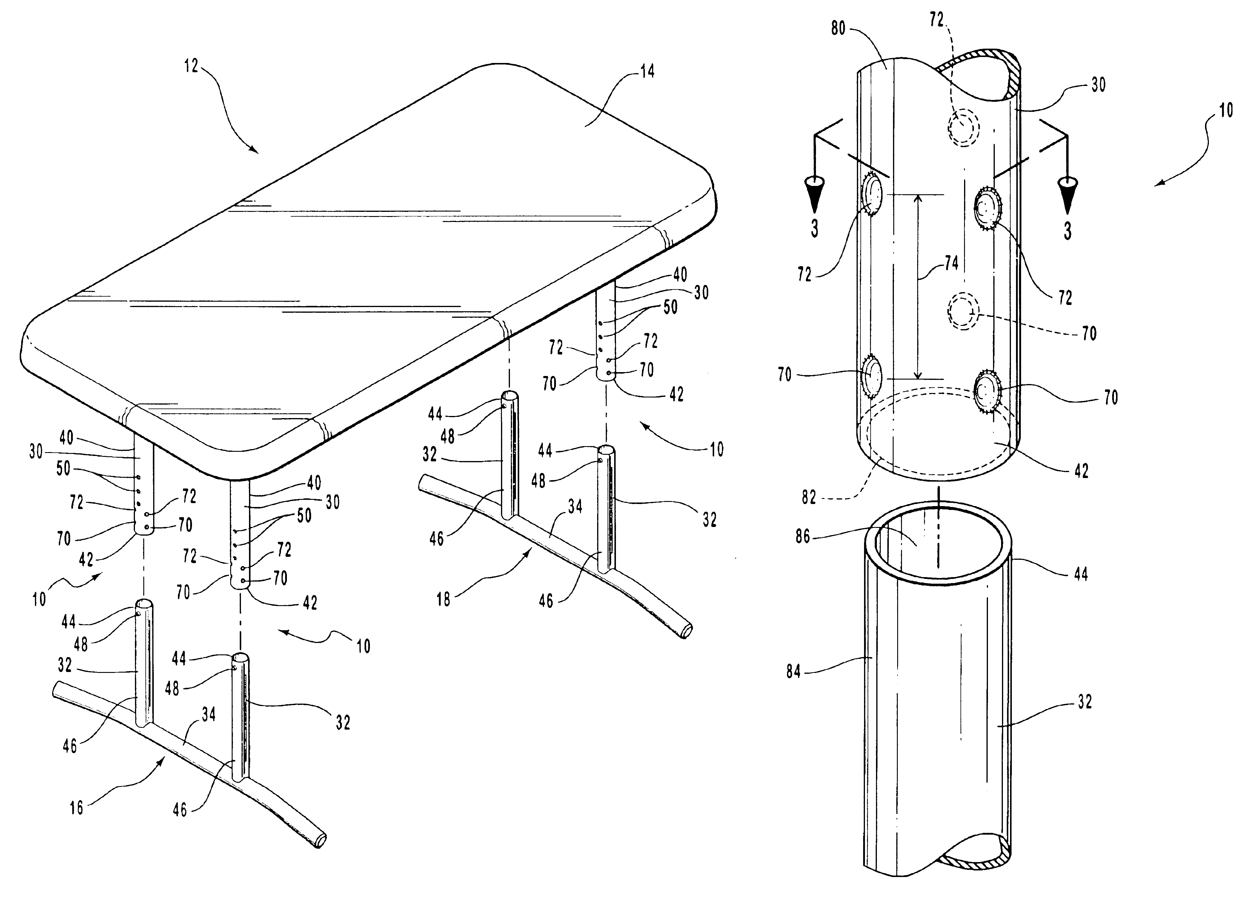
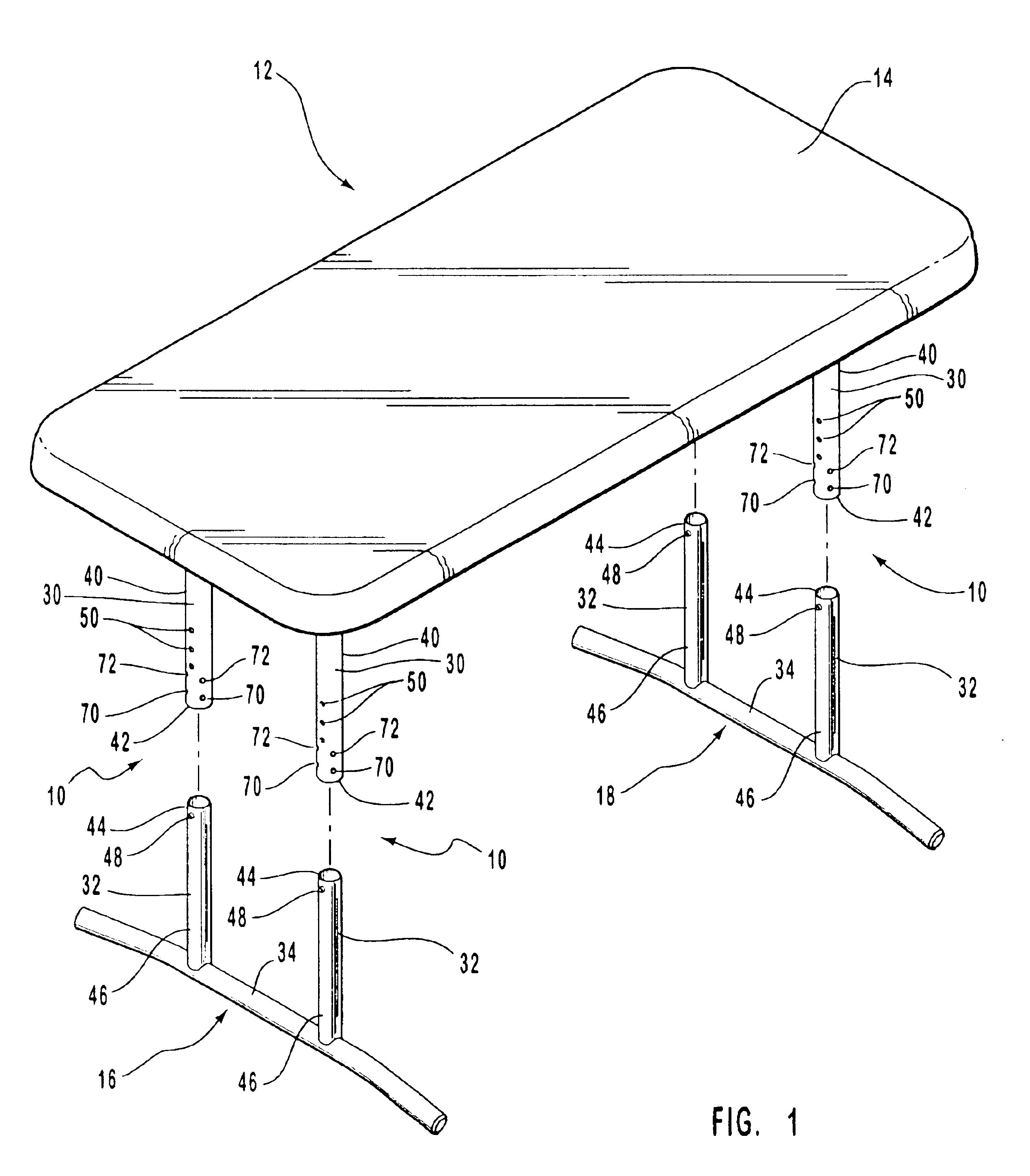
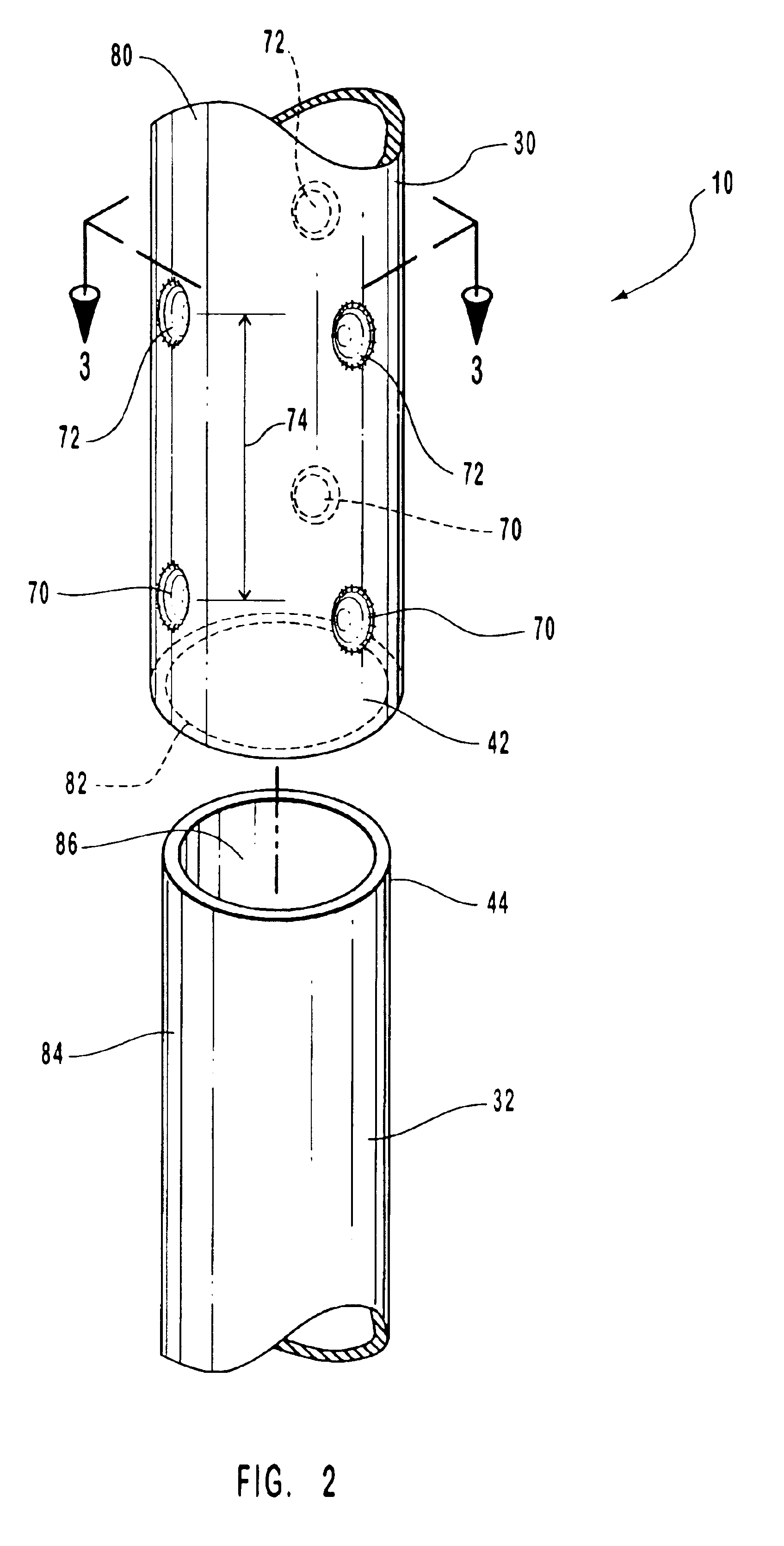
The present invention involves a telescoping assembly that is adjustable in length. Preferably, the telescoping assembly is used in connection with a table to create a table with an adjustable height. The principles of the present invention, however, are not limited to tables with adjustable height. It will be understood that, in light of the present disclosure, the telescoping assembly disclosed herein can be successfully used in connection with other types of tables, devices and mechanisms.

Additionally, to assist in the description of the telescoping assembly, words such as inner, outer, interior, exterior, distal and proximal are used to describe the accompanying figures. It will be appreciated, however, that the components of the present invention could be arranged into a variety of suitable configurations. A detailed description of various preferred embodiments of the telescoping assembly now follows.

As seen in FIG. 1, two telescoping assemblies 10 form part of a table 12 with ...


PUM


Abstract

A telescoping assembly allows the length of an assembly to be readily adjusted. Desirably, the telescoping assembly is used in connection with a table to allow the height of the table to be easily adjusted. The telescoping assembly preferably includes one or more projections formed in telescoping members and the projections provide accurate, low friction contact areas between the telescoping members. Preferably, first and second plurality of projections are provided, and these plurality of projections can be located on either the same telescoping member or different telescoping members. The plurality of projections are preferably evenly distributed about the telescoping members and separated by a given distance, but the projections may be located in any suitable positions and the telescoping assembly can have any appropriate number of projections.

Description

FIELD OF THE INVENTIONThe present invention generally relates to adjustable length members. More specifically, the adjustable length members telescopically engage each other and are preferably adjustable into a plurality of different lengths. Advantageously, the adjustable length members can be used to support a table at a desired height and the adjustable length members may form part of a table support assembly.DESCRIPTION OF RELATED ARTIn many devices, it is desirable to have a group of members, or an assembly, that is adjustable in length. A classic example of an assembly that is adjustable in length is a telescoping antenna. A conventional telescoping antenna includes several tubular members that allow the antenna to be retracted into a compact or storage position and extended into a use position. In greater detail, a conventional telescoping antenna includes a number of tubular members with different inner and outer diameters that allow the members to be nested together in the ...

Claims


Application Information

Patent Timeline
Patent Type & Authority Patents(United States)
IPC IPC(8): A47B9/14A47B9/00
CPCA47B9/14Y10T403/32475
Inventor STRONG, LYNN CURTIS
Owner LIFETIME PRODUCTS
Why Eureka
Try Eureka