
Buffer packing apparatus

a buffering and packaging technology, applied in the direction of packaging, containers to prevent mechanical damage, packaging, etc., can solve the problems of increasing the production cost of such designs, high mold development costs, and unfriendly polyurethane foam or emulsified polyethylene materials in packages, so as to achieve the effect of increasing the buffering

Inactive Publication Date: 2005-01-18
ARIMA COMP
View PDF6 Cites 31 Cited by
  • Summary
  • Abstract
  • Description
  • Claims
  • Application Information

AI Technical Summary

Benefits of technology

Accordingly, one object of the present invention is to provide a buffer packing apparatus for increasing the buffering effect between an object and a packaging box.
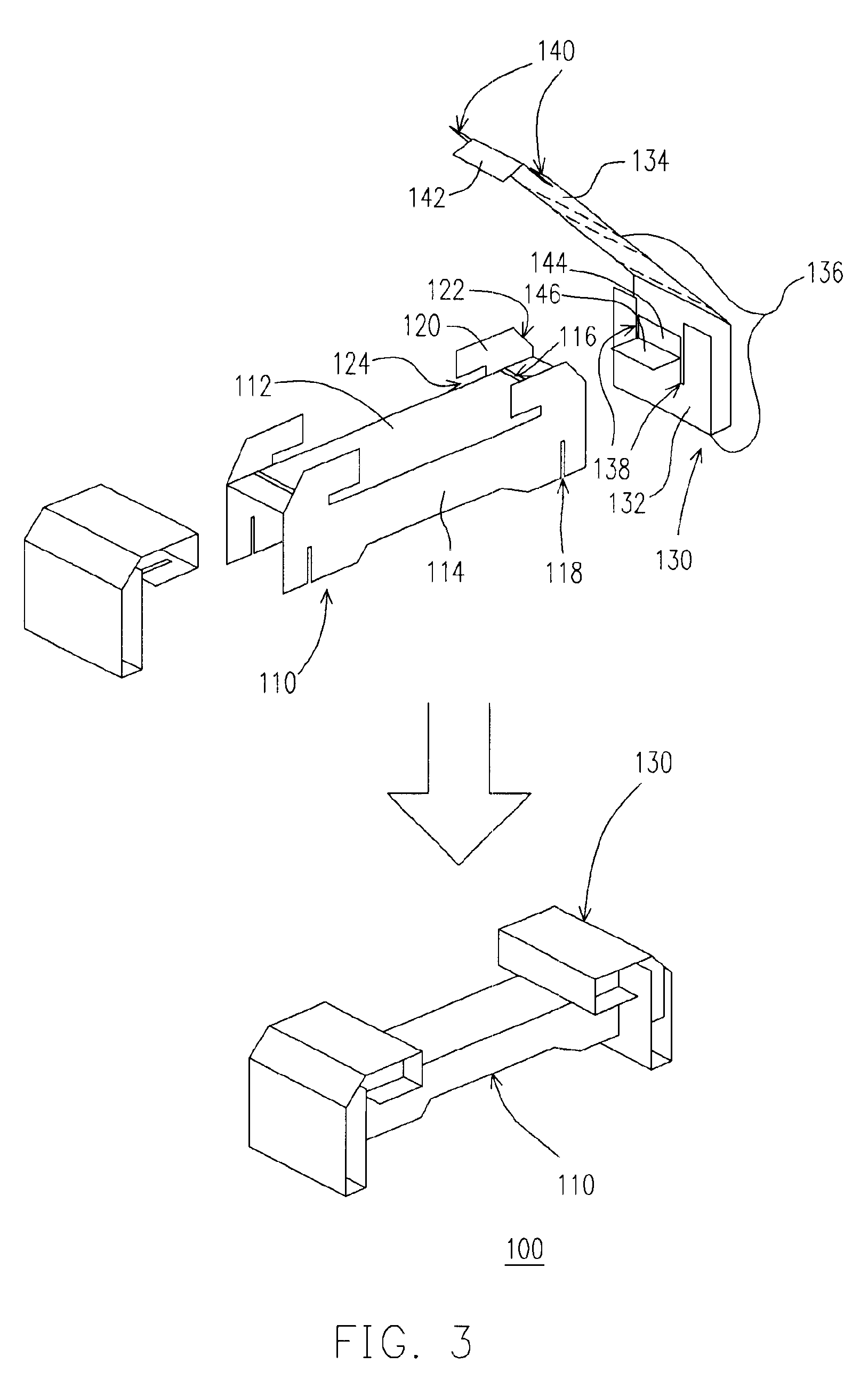
According to this invention, the buffer packing apparatus comprises a U-shaped column body and two buffering sleeves. The bumper plate and the first meshing board support and press against the four sides of a wrap object for housing the object on a horizontal plane. The distance separating the carrier boards is equal to the height of the object for supporting the object and limiting any movement of the object in the vertical direction. The buffering sleeves located at two ends of the U-shaped column body form a main buffering space for protecting the object against any damage resulting from an external impact. In addition, the chamfers on the buffering sleeves prevent a portion of the buffering sleeves from contacting the folded section of the packaging box. Hence, the buffering sleeves are prevented from a direct impact when any corner of the packaging box is hit. In other words, the buffer packing apparatus is strengthened structurally. In brief, the buffer packing apparatus of this invention not only has a simple apparatus but is also easy to fabricate. Moreover, the buffer packing apparatus can be easily modified to enclose objects having a different dimension. All that is required is simply to change the positions of the slots on the U-shaped column and adjust the width of the U-shaped column body.

Problems solved by technology

In recent years, with the issue of environmental protection in everybody's mind, polyurethane foam or emulsified polyethylene material in packages is considered environmentally unfriendly.
However, mold development is often expensive thereby increasing the production cost of such designs.
Hence, the paper buffer packing apparatus often has quite limited use.

Method used


Image

  • Buffer packing apparatus
  • Buffer packing apparatus
  • Buffer packing apparatus

Examples


Embodiment Construction

Reference will now be made in detail to the present preferred embodiments of the invention, examples of which are illustrated in the accompanying drawings. Wherever possible, the same reference numbers are used in the drawings and the description to refer to the same or like parts.

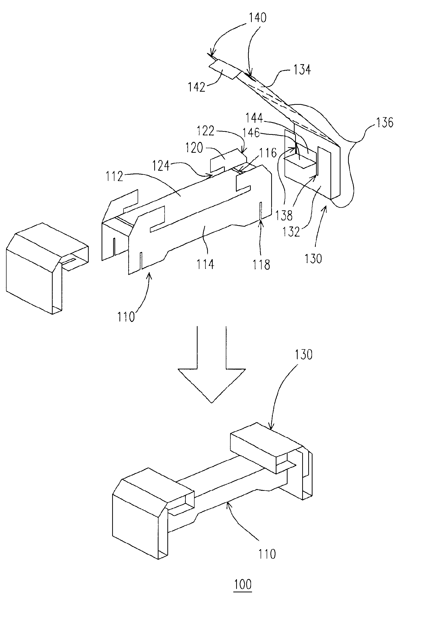
FIG. 3 is a perspective view showing the process of assembling a buffer packing apparatus according to this invention. The buffer packing apparatus 100 is fabricated using chevron paper, board paper or paper-like material, for example. As shown in FIG. 3, the buffer packing apparatus 100 comprises a U-shaped column body 110 and a pair of buffering sleeves 130. The U-shaped column body 110 furthermore comprises a bumper plate 112, a pair of carrier boards 114 and a pair of protruded sections 120. A groove 116 is extended between both ends of the bumper plate 112. The carrier boards 114 connect perpendicularly with the respective bumper plates 112. Furthermore, the ends of each carrier board 114 have a pair ...


PUM


Abstract

A buffer packing apparatus for packing an object and increasing the buffering capacity between the object and a packaging box is provided. The buffer packing apparatus comprises a U-shaped column body and a pair of buffering sleeves. The two carrier boards in the U-shaped column body support the upper and lower surface of the object. The buffering sleeves are engaged to the respective ends of the U-shaped column body to form a buffering space for protecting the object against external impact. The corners of the buffer packing apparatus are also chamfered to increase the buffering capacity of buffering sleeves when the packaging box receives an external impact.

Description

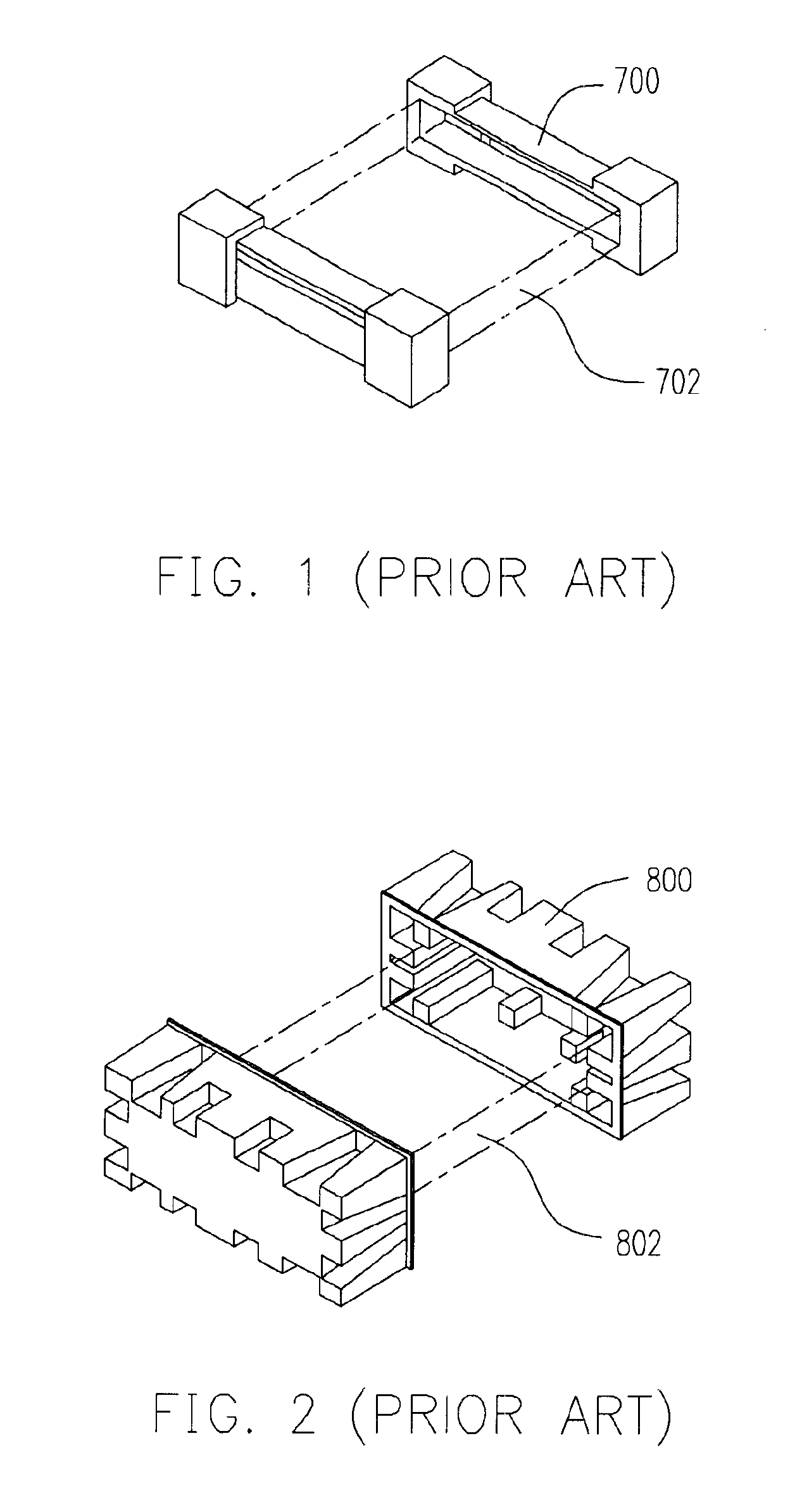
BACKGROUND OF INVENTION1. Field of the InventionThe present invention relates to a buffer packing apparatus. More particularly, the present invention relates to an easy-to-assemble and flexible buffer packing apparatus.2. Description of the Related ArtMost objects including notebook computers, CD-ROM or liquid crystal display (LCD) usually rely on a buffer packing apparatus to house the object inside a packaging box and provide buffering space for absorbing shock resulting from transportation. In the past, buffer packing apparatus frequently deployed polyurethane foam or emulsified polyethylene material because the material is light and easy to shape.FIG. 1 is a perspective view of a buffer packing apparatus fabricated using polyurethane foam or emulsified polyethylene (EPE). The buffer packing apparatus 700 is slid into opposite sides of a packing object 702 for securing the object and providing some buffering. Since emulsified polyethylene is more flexible and bendable than polyur...

Claims


Application Information

Patent Timeline
IPC IPC(8): B65D5/50
CPCB65D5/5069
Inventor LI, MING-WEIYU, CHIA-CHEN
Owner ARIMA COMP
Learn More