Flap valve

Inactive Publication Date: 2005-01-18
ROBERT BOSCH GMBH
View PDF10 Cites 1 Cited by
  • Summary
  • Abstract
  • Description
  • Claims
  • Application Information

AI Technical Summary

Benefits of technology

The flap valve according to the invention has the advantage of achieving a high degree of tightness during closing, with the least possible amount of torque. The flexibility of the valve tube and/or of the valve flap and also the tilting the valve tube and/or the valve flap produce a relatively balanced stress level in the flap valve during closing, which results in the fact that the flap valve has no mechanical stop within certain symmetrical boundaries despite the high degree of tightness. Due to the inclination of the tube end, a part of the flap contour is disposed outside of the valve tube during the movement of the valve flap, as a result of which only a partial contact is produced so that adjusting the valve flap requires only a very small amount of torque. Only during closing, when the flap geometry is approximately encompassed by the valve tube geometr

Problems solved by technology

As a result, the valve tube can favorably conform to the valve flap and at the same time, can also tilt to th

Method used


Image

  • Flap valve
  • Flap valve
  • Flap valve

Examples


Example

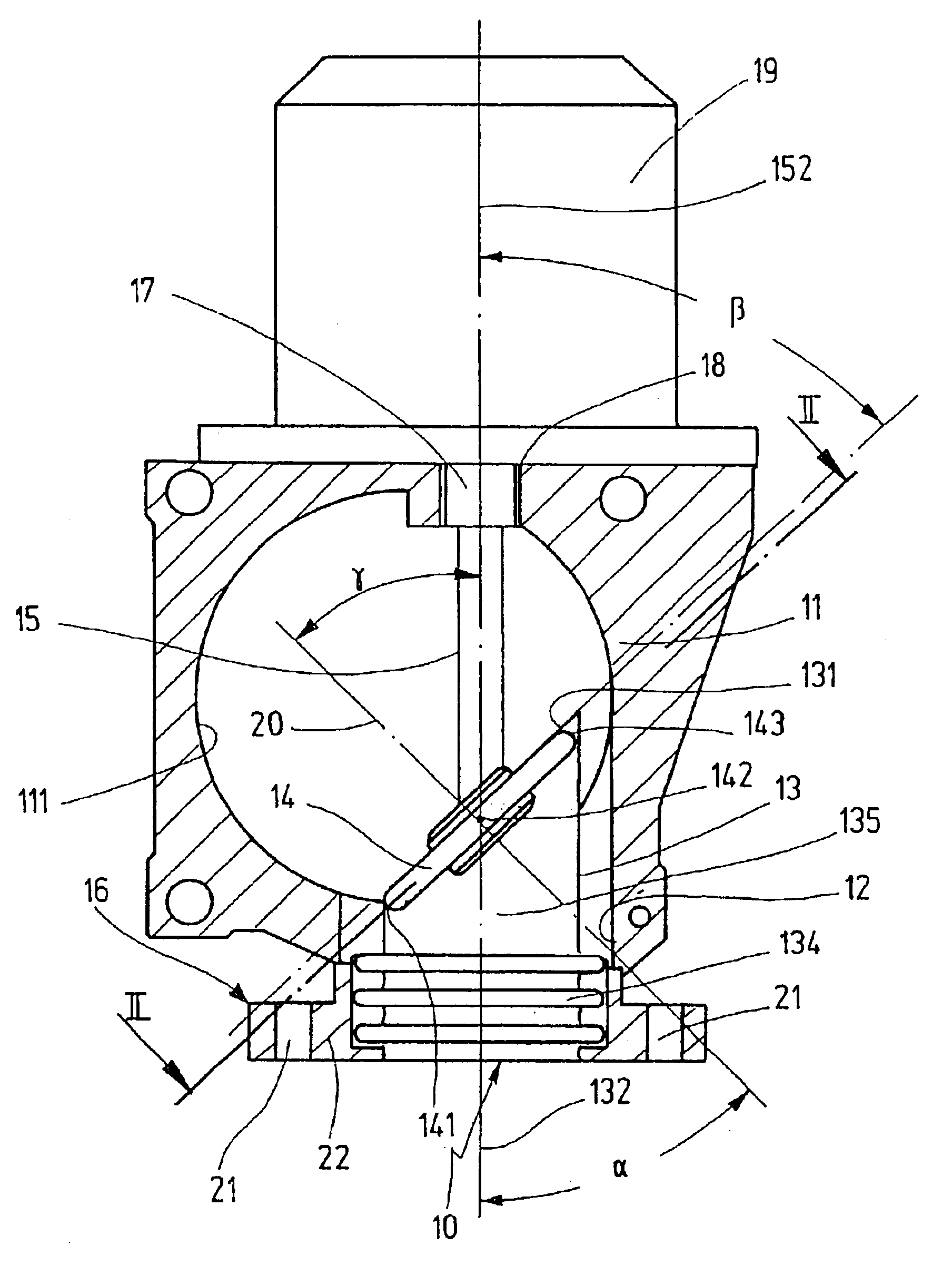
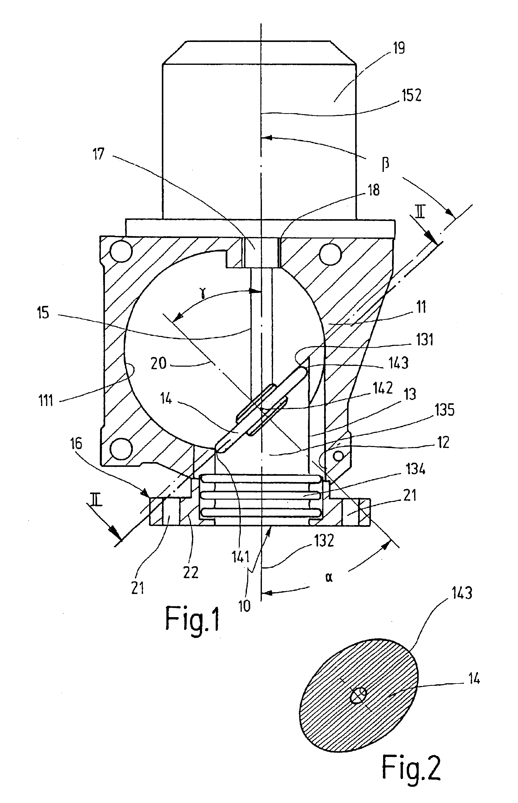
In the exemplary embodiment of FIG. 1, the flap valve 10 shown in a perspective view in FIGS. 3, 4, 6 and 7 is used as an exhaust return valve in the intake section of an internal combustion engine. This intake section includes an intake tube 11, which is for air leading to the internal combustion engine and usually contains a throttle valve, not shown here, for controlling the air flow. The casing of the intake tube 11 has an opening 12 let into it, whose axis is aligned at right angles to the axis of the intake tube 11.

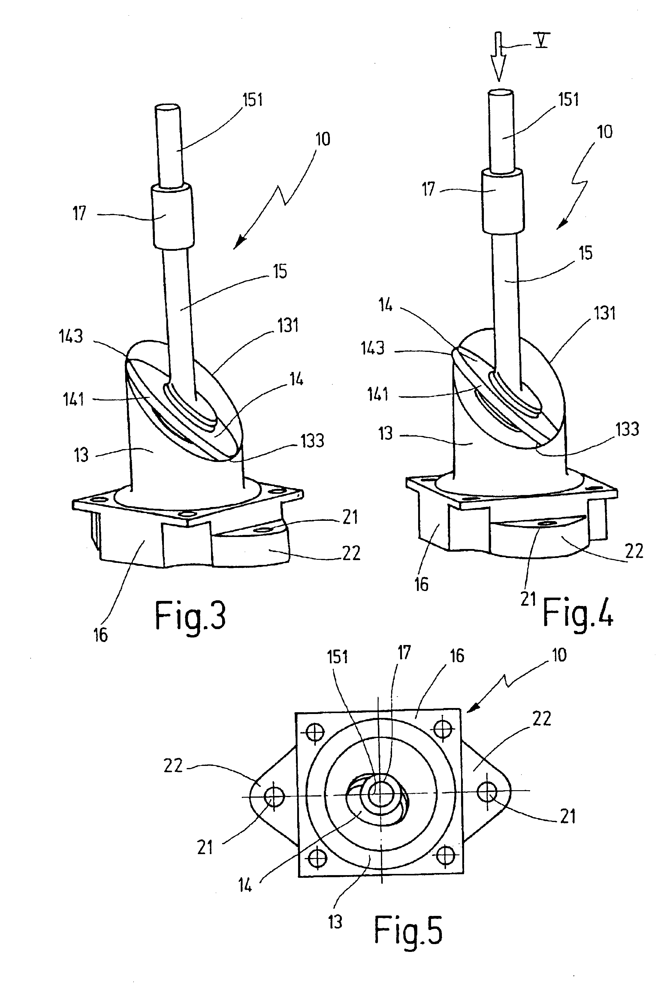
The flap valve 10 shown in a longitudinal section in FIG. 1 and in perspective views in FIGS. 3 and 4 has a thin-walled, flexible, possibly elastically deformable valve tube 13 with a controllable tube cross section 135 and a valve flap 14, which is disposed in the valve tube 13, is fastened to the end of a flap shaft 15 and, through rotation of the flap shaft 15, can be pivoted between an open position that unblocks the maximal tube cross section 135 of the valve t...


PUM


Abstract

In a flap valve for controlling a gas flow, with a valve tube that conveys the gas flow and a valve flap, which is disposed in the valve tube, is non-rotatably supported on an adjustable flap shaft, and can be pivoted between an open position that maximally unblocks the tube cross section and a closed position that blocks the tube cross section, in order to produce a high degree of tightness of the flap valve with the least possible torque, the tube end of the valve tube is inclined so that the circumferential tube edge is essentially disposed in a plane extending at an acute angle in relation to the tube axis. The valve flap has an approximately elliptical outer contour and is disposed in the valve tube at or near the inclined tube end so that its tube normal encloses an acute angle with the tube axis. The valve flap and/or the valve tube may be totally or partially embodied so that they can be elastically deformed and/or tilted.

Description

BACKGROUND OF THE INVENTION1. Field of the InventionThe invention is directed to an improved flap valve for controlling a gas flow and more particularly to such a valve especially useful in controlling the flow in a gas flow system of an internal combustion engine.2. Description of the Prior ArtIn a known throttle valve for controlling a gas flow in an exhaust conduit of an internal combustion engine, disclosed in DE 43 05 123 A1, the flap shaft which supports the throttle valve and extends parallel to the flap surface of the throttle valve is supported at both ends by a bearing bore in the conduit wall of the exhaust conduit and respectively protrudes through a bearing sleeve there. In order to achieve a greater degree of tightness while avoiding a sluggishness of the flap actuation, the bearing sleeves, which are each axially prestressed by means of spring force in a respective bearing housing, can move in a radial direction inside the bearing housing, as a result of which the dim...

Claims


Application Information

Patent Timeline
IPC IPC(8): F02D9/10F02D9/08F02M25/07F16K1/22F16K1/18F16K27/02
CPCF02D9/101F02M25/0773F16K1/225F02M25/0793Y02T10/121F02M26/54F02M26/70
Inventor KNAUSS, UWE
Owner ROBERT BOSCH GMBH
Why Eureka
Try Eureka