Self-contained, portable inspection system and method

a mobile inspection and self-contained technology, applied in the direction of material analysis, material analysis using wave/particle radiation, instruments, etc., can solve the problems of not being able to easily modify, space is generally in substantial demand and short supply, and the scenario is not typically feasible, so as to reduce the wear-tear of the truck engine, reduce operational stress, and optimize the effect of fuel consumption

Inactive Publication Date: 2005-01-18
RAPISCAN SYST INC (US)
View PDF14 Cites 219 Cited by
  • Summary
  • Abstract
  • Description
  • Claims
  • Application Information

AI Technical Summary

Benefits of technology

The inspection methods and systems of the present invention are mobile, rapidly deployable, and capable of scanning a wide variety of receptacles cost-effectively and accurately on uneven surfaces. In a first embodiment, a self-contained inspection system comprises an inspection module that, in a preferred embodiment, is in the form of a mobile trailer capable of being towed and transported to its intended operating site with the help of a tug-vehicle. The tug-vehicle can serve as a support and carrier structure for at least one source of electromagnetic radiation. A hydraulic lift system is used to load and unload the at least one source and, preferably, one radiation shield plate is positioned on the back of the driver cabin of the tug-vehicle to protect the driver from first order scatter radiation. The inspection module is custom-built as a mobile trailer and can provide support for a plurality of detector arrays and a boom to deploy power cable to at least one source of radiation during operation. If a high energy radiation source is used, the inspection module can be a separate trailer / truck with equipment to transfer data from and to detector / source module.
The methods and systems of the present invention represent substantial improvements over the prior art. Conventionally, trucks supporting a scanner system were required to move the full weight of the scanner, regardless of the size and load of the OUI. In the preferred embodiments of the present invention, the source-detector system remains stationary and the OUI is moved, enabling optimized fuel consumption, decreases in the wear-tear of the truck engine, a reduction in operational stress, decreases in the repairing of sub-systems such as the tug mechanism, and a simpler overall design.
Furthermore, in conventional systems, the distance between the X-ray beam and driver remains fixed thereby increasing the risk of exposing the driver to scatter radiation, particularly, in case of a lightly loaded OUI. In the preferred embodiments of the present invention, the radiation source may be controlled to emit only after the tug-truck has passed the beam location, putting the driver at a convenient distance from the area with scatter radiation. With the scatter shield on the back to protect driver from first order scatter and because the driver is moving away from the radiation area during the scanning process, the driver's total radiation exposure will be minimized.
The present invention has additional operational benefits, including flexible scheduling. Where multiple portable inspection units are present, parts can be more readily interchanged to enable the swapping on non-functional parts for repair while still insuring units are available for inspection. For example, if truck-1 / trailer-1 has an X-ray generator problem and truck-2 / truck-2 has a problem with its detector system, the trailer-1 can be hitched to truck-2 to get a functional unit.

Problems solved by technology

However, these scenarios are not typically feasible.
Space is generally in substantial demand and short supply.
Existing ports operate under a routine that is not easily modified without causing disruption to the entire infrastructure of the port.
With limited space and a need to expand, finding suitable space to accommodate additional inspection facilities along the normal process route remains difficult.
Additionally, selected locations are not necessarily permanent enough for port operators to commit to.
In either case the building footprint is significant depending upon the size of cargo containers to be inspected.
This limits the flexibility of dismantling the entire system for optimum portability and adjustable deployment to accommodate a wide array of different sized cargo, shipments, vehicles, and other containers.
As a result these systems can be complicated to deploy and pose several disadvantages and constraints.
For example, in a moving-scan-engine system the movement of the source and detector, relative to a stationary object, may cause lateral twist and lift and fall of the detector or source, due to movement of the scanner over uneven ground, inducing distortions in the scanned images and faster wear and tear of the scanner system.
Such systems that require a detector-mounted boom to unfold during deployment may cause an unstable shift of the center of gravity of the system off the base, causing the system to tip over.
Further, in case of moving-scan-engine systems using a “swing arm” boom approach, the driver driving the scanner truck is unable to gauge the possibility of hitting the detector box, mounted on a boom, with a vehicle under inspection (VUI), as the detector box is on the other side of the VUI during scanning and not visible to the driver.
Additionally, with moving-scan-engine systems, the truck supporting the scanner system is always required to move the full weight of the scanner regardless of the size and load of the VUI, putting greater strain on the scanning system.
Further, because of the integrated nature of prior art systems, swapping detector and radiation systems between scanning systems is not feasible.

Method used


Image

  • Self-contained, portable inspection system and method
  • Self-contained, portable inspection system and method
  • Self-contained, portable inspection system and method

Examples


Embodiment Construction

The inspection methods and systems of the present invention are mobile, rapidly deployable, and capable of scanning a wide variety of receptacles cost-effectively and accurately on uneven surfaces. Reference will now be made in detail to specific embodiments of the invention. While the invention will be described in conjunction with specific embodiments, it is not intended to limit the invention to one embodiment.

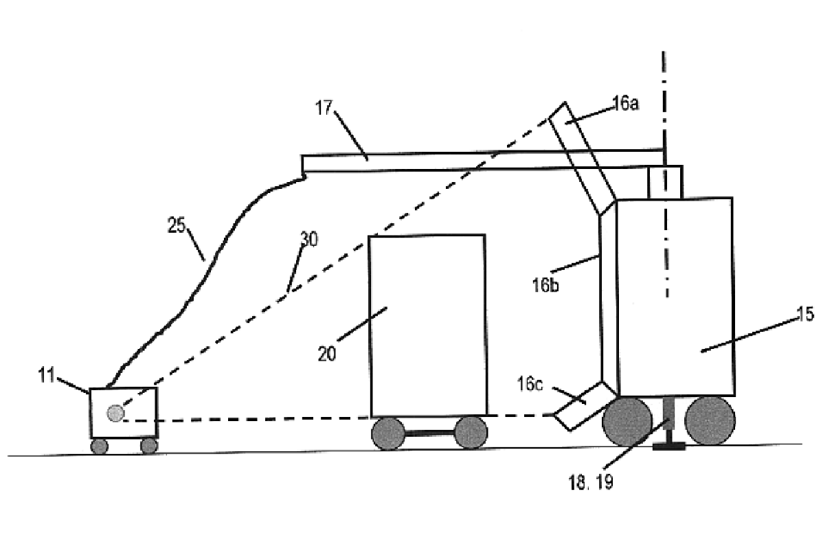
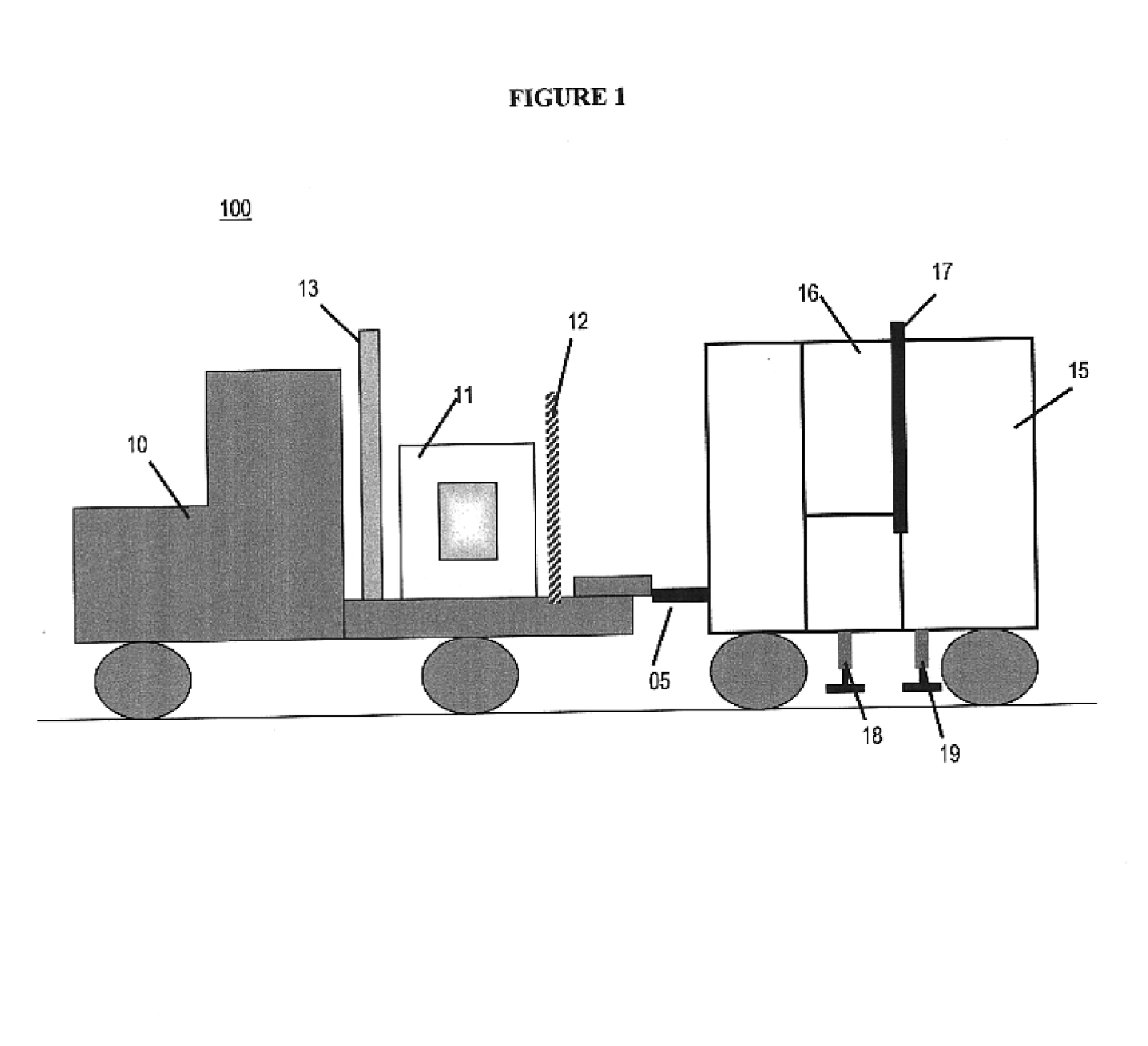
FIG. 1 shows a perspective view of an exemplary self-contained inspection system 100. The system 100 comprises of an inspection module 15 that, in a preferred embodiment, is in the form of a mobile trailer capable of being towed and transported to its intended operating site with the help of a tug-vehicle 10. While the present invention is depicted as a tug vehicle 10 connected to a trailer 15, one of ordinary skill in the art would appreciate that the vehicular portion of the system and inspection module portion of the system could be integrated into a single mobile struct...


PUM

PropertyMeasurementUnit
angleaaaaaaaaaa
angleaaaaaaaaaa
velocityaaaaaaaaaa

Abstract

The inspection methods and systems of the present invention are mobile, deployable, and capable of scanning a wide variety of receptacles cost-effectively and accurately on uneven surfaces. The inspection system comprises an inspection module that, in a preferred embodiment, is in the form of a mobile trailer capable of being towed and transported to its intended operating site with the help of a tug-vehicle. The tug-vehicle preferably includes at least one source of electromagnetic radiation, a hydraulic lift system to load and unload the radiation source, and at least one radiation shield plate positioned on the back of the driver cabin of the tug-vehicle.

Description

FIELD OF THE INVENTIONThe present invention relates generally to a self-contained mobile inspection system and method and, more specifically, to improved methods and systems for substantially stable scanning on uneven site surfaces, enabling better visibility of false compartments and enhanced inspection throughput.BACKGROUND OF THE INVENTIONX-ray systems are used for medical, industrial and security inspection purposes because they can cost-effectively generate images of internal spaces not visible to the human eye. Materials exposed to X-ray radiation absorb differing amounts of X-ray radiation and, therefore, attenuate an X-ray beam to varying degrees, resulting in a transmitted level of radiation that is characteristic of the material. The attenuated radiation can be used to generate a useful depiction of the contents of the irradiated object. A typical single energy X-ray configuration used in security inspection equipment may have a fan-shaped or scanning X-ray beam that is tr...

Claims


Application Information

Patent Timeline
Patent Type & Authority Patents(United States)
IPC IPC(8): G01N23/04G01N23/02G01V5/00
CPCG01V5/0008G01N23/04
Inventor LE, KHAIKOTOWSKI, ANDREAS F.
Owner RAPISCAN SYST INC (US)
Why Eureka
Try Eureka