Getter for enhanced micromechanical device performance

a technology of micromechanical devices and getters, which is applied in the direction of dispersed particle separation, other chemical processes, separation processes, etc., can solve the problems of not perfectly sealing out these elements over the life of the device, unsatisfactory use of existing getters compounds by many modern micromechanical devices

Inactive Publication Date: 2005-01-18
TEXAS INSTR INC
View PDF19 Cites 102 Cited by
  • Summary
  • Abstract
  • Description
  • Claims
  • Application Information

AI Technical Summary

Benefits of technology

According to yet another embodiment of the disclosed invention, an image projection system is disclosed. The image projection system comprises a light source providing a beam of light along a light path, a micromirror on the light path, the micromirror device selectively reflecting portions of the beam of light in response to image data and control signals, and projection optics receiving the selectively reflected portions of the beam of light and focusing the selectively reflected portions of the beam of light onto an image plane. The micromirror device in the projection system comprising, a micromechamical machine; a package enclosing the micromechanical machine, and a desiccant compound enclosed by the package. The desiccant compound is able to reversibly absorb a carboxylic acid passivation material. The desiccant compound comprising a polymer binder selected from the group consisting of polysaccharides, polyamines, polyamides, and polysulfones and a drying agent dispersed in the binder at a polymer to drying agent weight ratio of 1:2.1 to 1:100.

Problems solved by technology

The hermetic packages, however, do not perfectly seal out these elements over the life of the device.
Existing getter compounds are unsatisfactory for use with many modern micromechanical devices.
Because of their small size, often less than 100 microns, micromechanical devices are very susceptible to damage from debris inside the micromechanical device package.
For example, debris can easily obstruct the motion of, or electrically short-circuit, micromirror elements which are often no larger than 17 microns.
This metal-to-metal contact can create sticking and friction (stiction) between the moving components.
Stiction becomes worse as the contacting surfaces wear against each other since the contact area is increased.
Unfortunately, the PFDA forms a relatively weak bond between with the aluminum surfaces on which it is deposited.
Without replenishment, exposed aluminum regions grow and eventually create unacceptably large stiction forces—ruining the device.
Additional PFDA, however, cannot simply be included in the package since the excess PFDA will condense in crystalline form on the working surfaces of the device, thereby forming particles that obstruct the free operation of the device and causing catastrophic device failure.

Method used


Image

  • Getter for enhanced micromechanical device performance
  • Getter for enhanced micromechanical device performance

Examples


Embodiment Construction

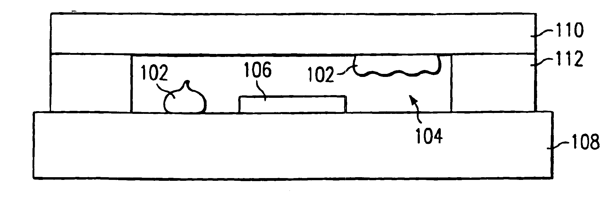
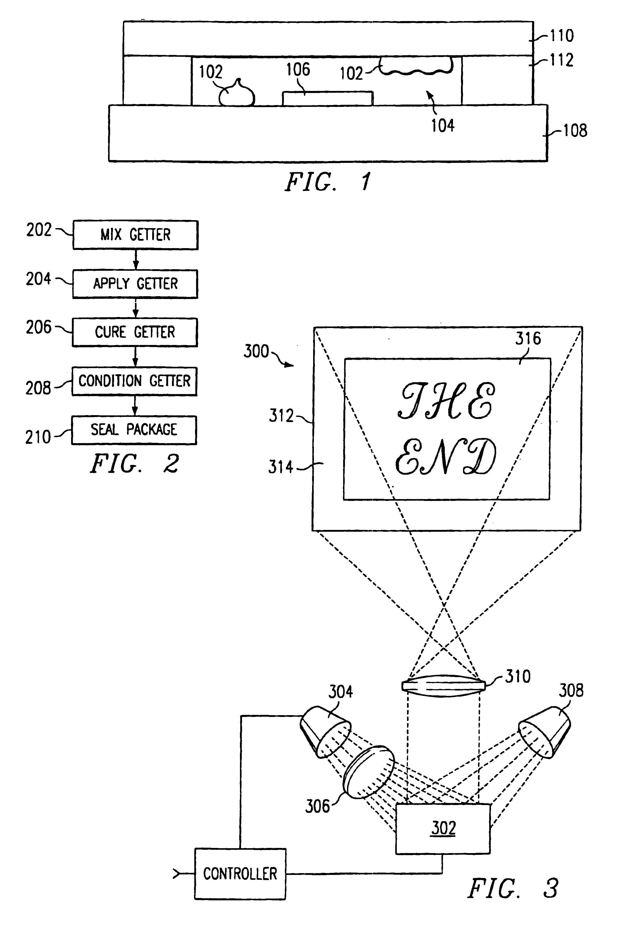
A novel getter, or desiccant, compound and method is disclosed. The disclosed getter, or desiccant, compound 102, shown in FIG. 1, performs a desiccation function as well as providing a reversible source / sink of passivation material in a headspace 104 in which a micromechanical device 106 is enclosed. While the following description describes its use with a PFDA surface treatment material and micromirror device, these examples are for illustration purposes and in no way limit the intended scope of the disclosed invention. The disclosed technology is ideal for any micromechanical device used with an acidic passivant.

The disclosed desiccant compound has two primary components, a polymer and a drying agent. The polymer acts as both a source and a sink for the surface passivation material, and holds the drying agent in place. The drying agent absorbs water vapor present in the enclosure.

Several classes of polymers are available for use in the disclosed desiccant compound. The preferred ...


PUM

PropertyMeasurementUnit
sizeaaaaaaaaaa
temperaturesaaaaaaaaaa

Abstract

A desiccant compound, image projection system using the desiccant compound, and a method for utilizing the desiccant compound. The desiccant compound formed by mixing (202) a polymer binder selected from the group consisting of polysaccharides (including without limitation structural polysaccharides such as cellulose, chitin, and their functionalized derivatives), polyamines, polysulfones, and polyamides with a drying agent, typically a zeolite, at a polymer to drying agent weight ratio of 1:2.1 to 1:100, or 1:4 to 1:10. After the desiccant compound is mixed (202) it is applied (204) to a surface and cured (206), often through the application of heat and vacuum. The cured desiccant compound is conditioned (208) and the it package is sealed (210).

Description

FIELD OF THE INVENTIONThis invention relates to the field of getters or desiccant compounds, particularly to moisture and particulate getters for micromechanical devices and electronic enclosures.BACKGROUND OF THE INVENTIONElectronic devices such as integrated circuits are often packaged in hermetically sealed enclosures. These enclosures protect the device from contaminants, particles, and water vapor that would otherwise enter the package and mechanically damage or electrically disrupt the device. The hermetic packages, however, do not perfectly seal out these elements over the life of the device. Additionally, some water vapor and debris is present in the enclosure cavity when the enclosure is sealed, or evolved by the packaging materials as the materials cure.Getters, compounds that capture contaminants, moisture vapor, and particles, are included inside the device enclosures to trap these species and preclude degradation of device performance, thereby increasing the operational...

Claims


Application Information

Patent Timeline
Patent Type & Authority Patents(United States)
IPC IPC(8): C09K3/00B01D53/28
CPCB01D53/28
Inventor JACOBS, SIMON JOSHUA
Owner TEXAS INSTR INC
Why Eureka
Try Eureka