Maximum power point tracking method and device

a tracking method and power point technology, applied in the direction of electric variable regulation, process and machine control, instruments, etc., can solve the problems of severe affect on the output monitor of the switching converter, the quantization error in the analog-digital conversion, and the control circuit in the above methods that measure the voltage and current of the solar cell and calculate their product are complicated and expensive, etc., to achieve the effect of improving energy utilization efficiency, reducing cost and realizing inexpensively

Inactive Publication Date: 2005-01-18
NAT INST OF ADVANCED IND SCI & TECH +1
View PDF13 Cites 344 Cited by
  • Summary
  • Abstract
  • Description
  • Claims
  • Application Information

AI Technical Summary

Benefits of technology

The circuit that performs tracking of the power point in the maximum power point tracking comprises mainly a simple pulse generator, an amplifier, and semiconductor switches and can be realized inexpensively using a small number of general-use parts.
Further, by using the method of this invention, it is possible to obtain the maximum output power generation in a direct-current power source at a lower cost, energy utilization efficiency is improved, and the recovery period for equipment investment cost can be shortened.

Problems solved by technology

However, the control circuits in the above methods that measure the voltage and current of the solar cell and calculate their product are complicated and expensive.
There is also a problem with quantization error in the analog-digital conversion.
Further, the method that monitors the output of the switching converter is severely affected by fluctuation in the load.

Method used


Image

  • Maximum power point tracking method and device
  • Maximum power point tracking method and device
  • Maximum power point tracking method and device

Examples


Embodiment Construction

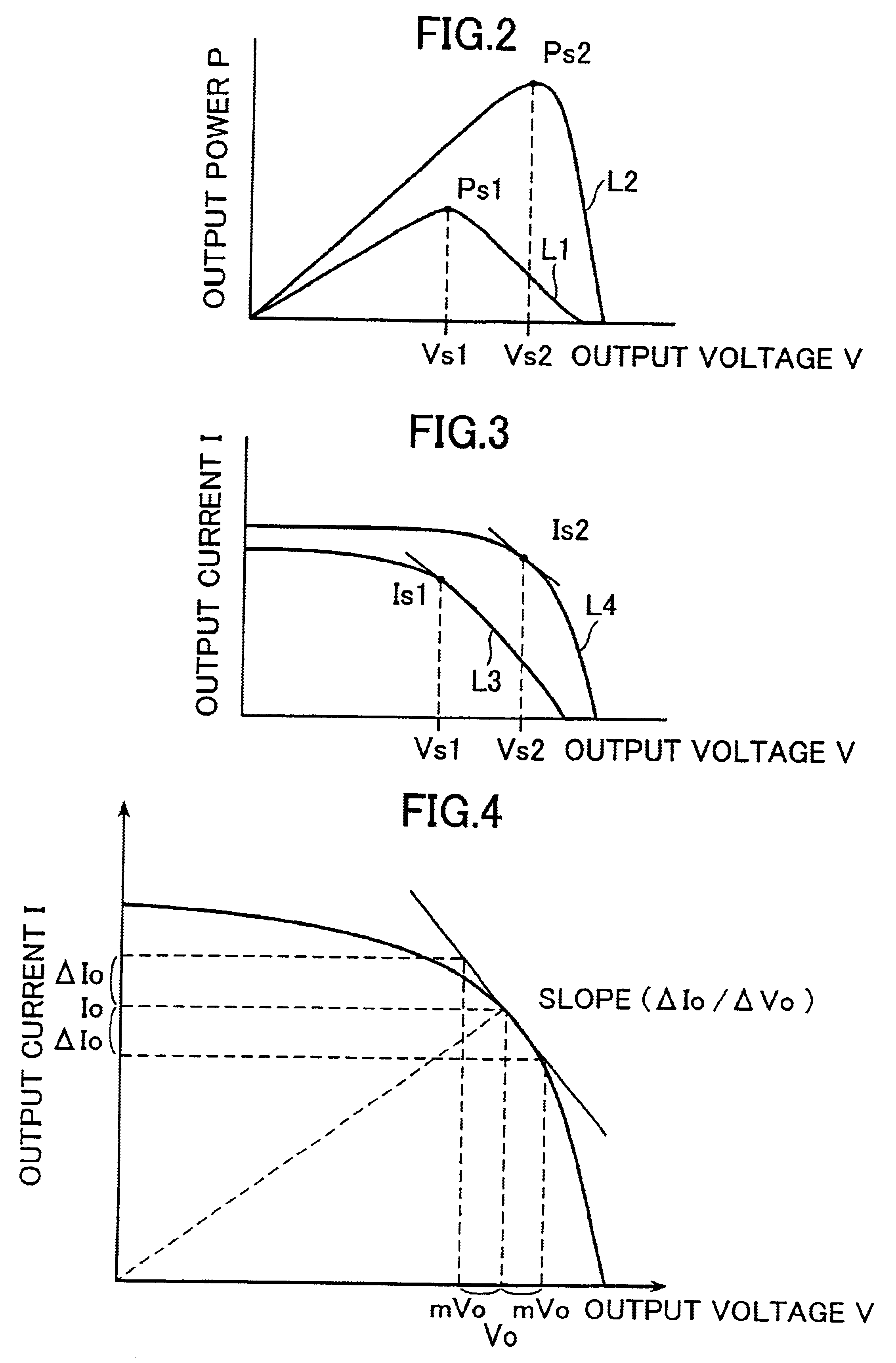
First, the characteristics of the direct-current power source, having a bow-shaped current-voltage characteristic and upon which this invention is premised, are explained. FIG. 2 shows the output power vs. output voltage characteristic (P−V) of a solar cell, and FIG. 3 shows the output current vs. output voltage characteristic (I−V) of the solar cell. In the current-voltage characteristic of a direct-current power source such as a solar cell, the current tends to decrease as the voltage increases, i.e., it has a bow-shaped characteristic that tends to drop off (this is referred to simply as a bow-shaped characteristic in this specification below). The output characteristic of a solar cell will vary with changes in the ambient temperature of the solar cell or the intensity of sunlight accompanying seasonal changes, etc. As the ambient temperature of the solar cell decreases, the characteristic curves will change from L1 to L2 and from L3 to L4, and as the intensity of sunlight decrea...


PUM


Abstract

The output current value of a direct-current power source obtained by low-frequency, minute modulation of the input voltage of a switching converter is detected in a circuit having an amplification factor switching function that switches the amplification factor between definite magnitudes synchronizing with the modulation, and by using a signal obtained by demodulating in a discriminator circuit the output of this circuit synchronizing with the modulation to control the switching converter, the power point of the switching converter can be tracked to the maximum power point by following the change in state of the direct current power source.

Description

BACKGROUND OF THE INVENTION1. Field of the InventionThis invention relates to a method and a device for implementing the method that tracks the optimal maximum power point in a system that supplies power from a direct-current power source, such as that generated by a solar cell array (photovoltaic generator), etc., which has a bow-shaped current-voltage characteristic, to a load via a switching converter so that the output power of the direct-current power source is maximized with respect to changes, etc., in the direct-current power source characteristic by controlling the operating point of the switching converter. The solar cell array (photovoltaic generator) shown above is hereinafter referred to simply as a solar cell.2. Description of the Prior ArtA prior art method that controls the power point (operation point) so that the power generated by the solar cell is maximized measures the voltage and current of the solar cell, performs an analog-digital conversion of those values a...

Claims


Application Information

Patent Timeline
Patent Type & Authority Patents(United States)
IPC IPC(8): G05F1/66G05F1/67H02J7/35H02M3/04H02M3/156H02M3/155
CPCG05F1/67H02J7/35H02M3/156Y02E10/58Y02E10/566Y02E10/56
Inventor KASAI, YUJIKANO, FUMIHISA
Owner NAT INST OF ADVANCED IND SCI & TECH
Why Eureka
Try Eureka