
Multi-beam scanning device

a scanning device and beam waist technology, applied in the field can solve the problems of deteriorating the imaging quality affecting the accuracy of multi-beam scanning devices, and wasting a lot of labor hours, so as to reduce the variation of the size of the spots formed on the object surface due to decentering of optical elements

Inactive Publication Date: 2005-01-18
ASAHI KOGAKU KOGYO KK
View PDF2 Cites 12 Cited by
  • Summary
  • Abstract
  • Description
  • Claims
  • Application Information

AI Technical Summary

Benefits of technology

In the multi-beam scanning device arranged as described above, the inclination of the image plane against the object surface due to the decentering of the optical elements due to manufacturing error and / or assembling error can be corrected by adjusting the direction into which the deflecting element deflects the laser beams. Thus, the size variation of the spots formed on the object surface due to decentering of the optical elements can be reduced.

Problems solved by technology

Thus, the displacement of the beam waist position of the laser beam most apart from the optical axis becomes extremely large when the additional deflector fully shifts the laser beams.
This causes an unacceptable size difference among the spots formed on the object surface, which deteriorates the imaging quality of the multi-beam scanning device.
Such methods, however, require much labor hour, which decreases the production efficiency of the multi-beam scanning device.
Since the additional deflector changes the laser beam shifting distance in accordance with the variation of the moving rate of the object surface, the size of the spots formed on the object surface also changes in accordance with the moving rate of the object surface, which causes deterioration of the imaging quality of the multi-beam scanning device.

Method used


Image

  • Multi-beam scanning device
  • Multi-beam scanning device
  • Multi-beam scanning device

Examples


Embodiment Construction

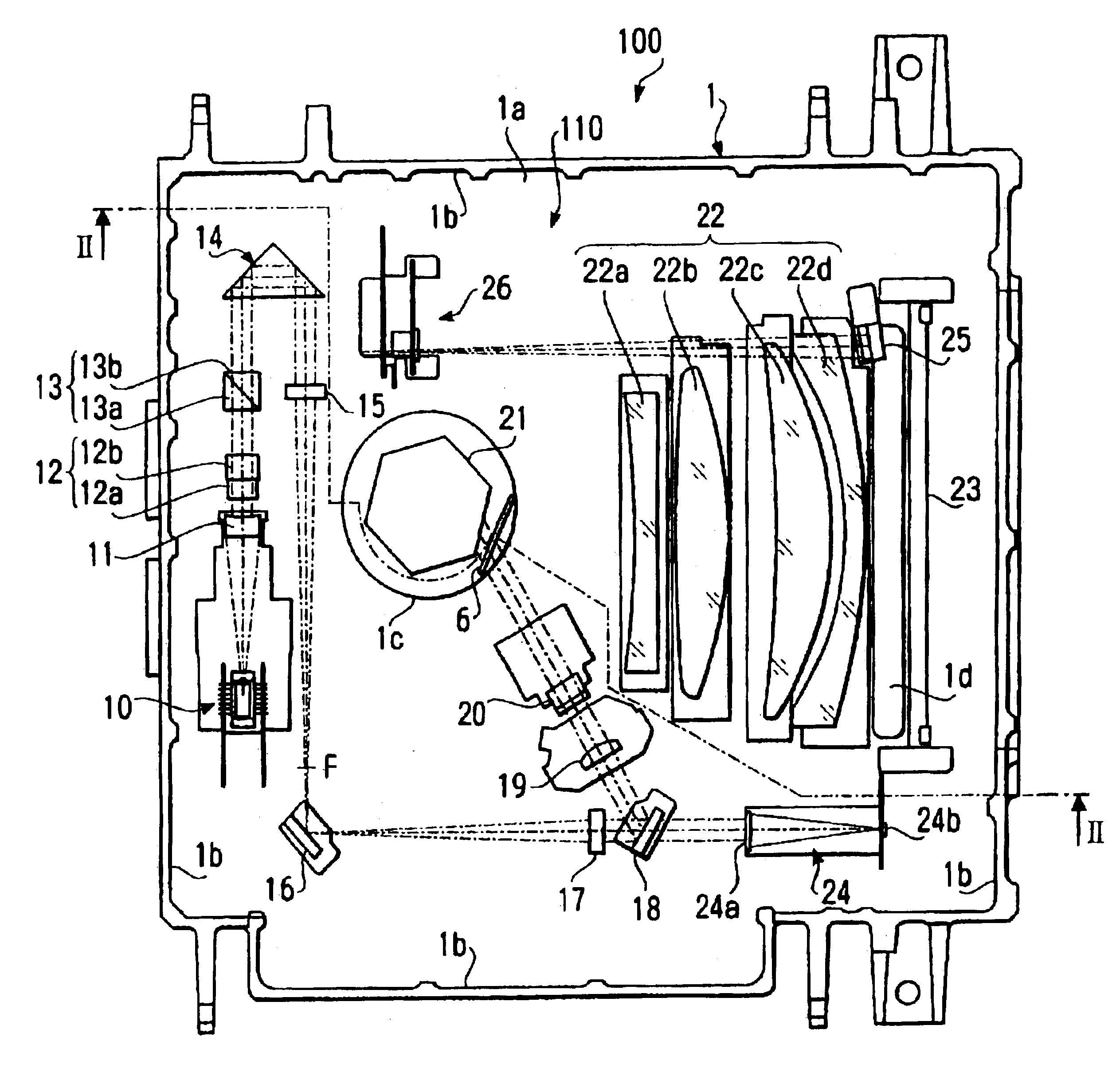
Hereinafter, an embodiment of the present invention will be described with reference to the accompanying drawings. The embodiment described is directed to a multi-beam scanning unit 100 that can be utilized for a laser image forming device such as a laser printer, laser copy apparatus, laser facsimile apparatus, a laser photo-plotter, and a direct imager.

General Configuration

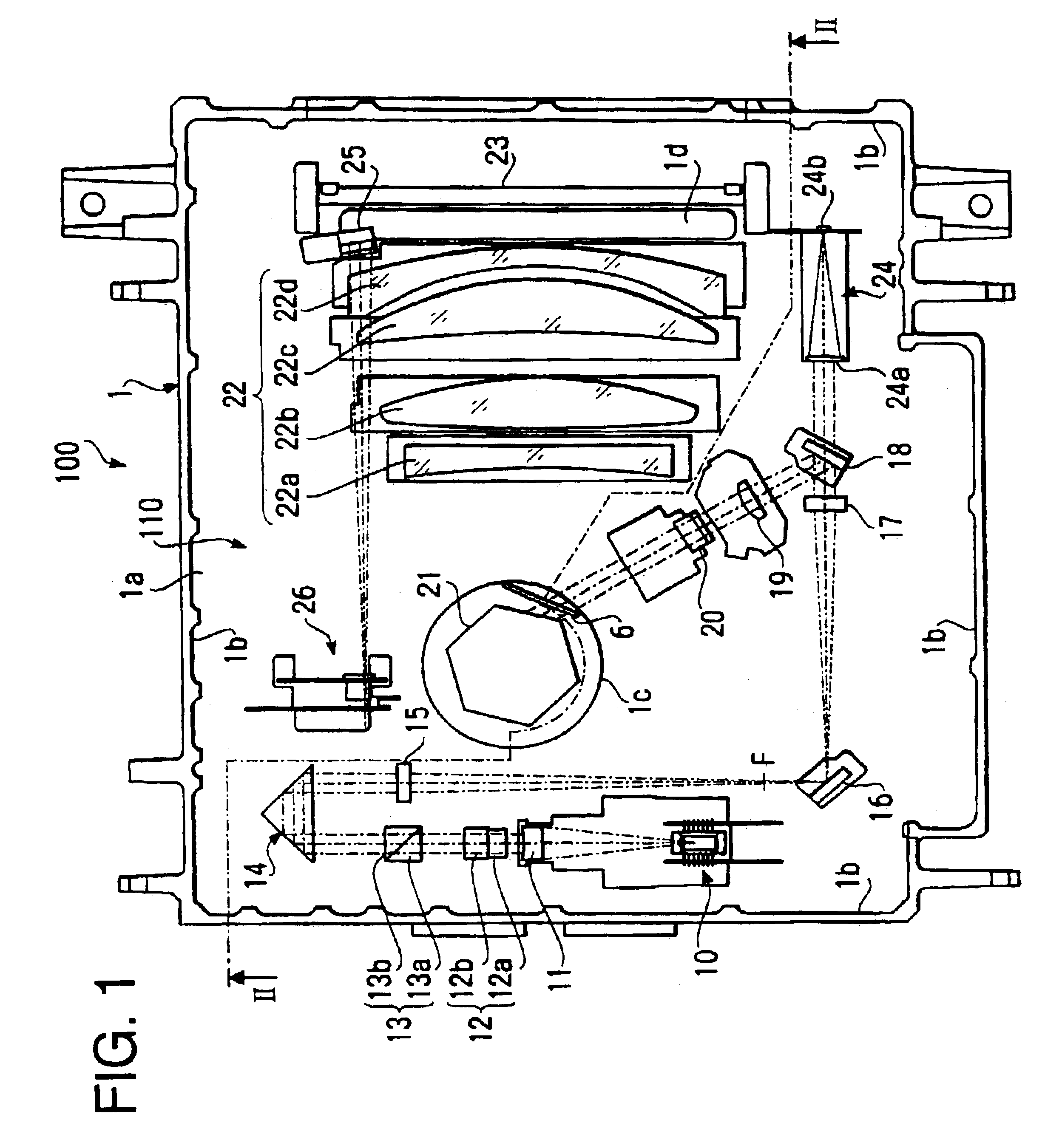
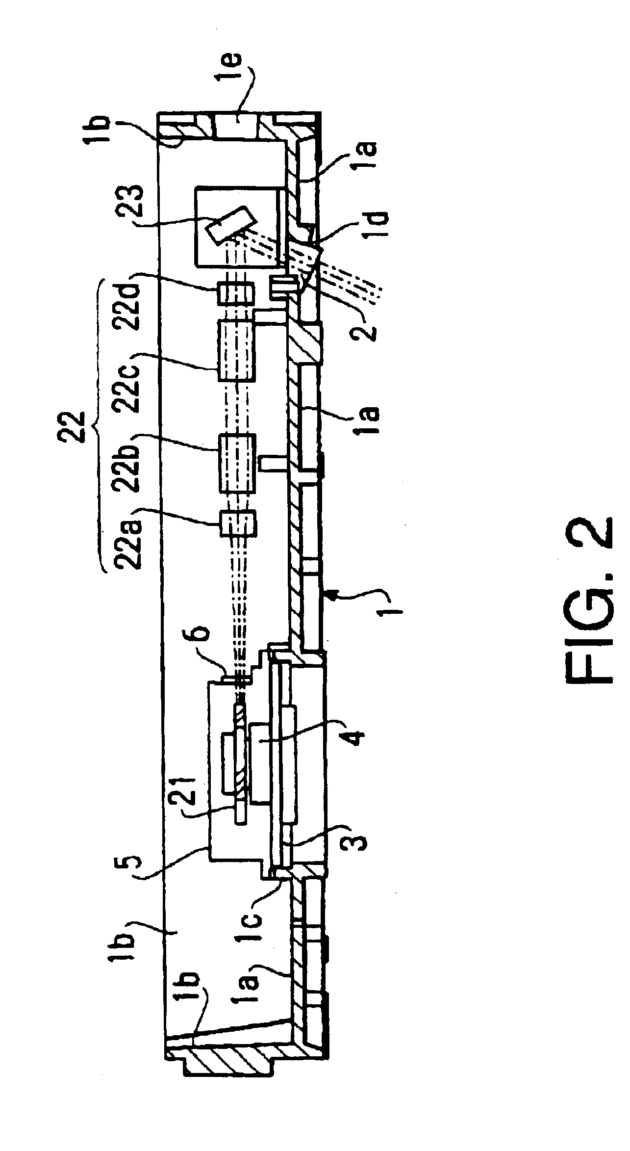
FIG. 1 schematically shows a plan view of the multi-beams scanning device 100, FIG. 2 is a sectional view of the multi-beams scanning device 100 shown in FIG. 1 taken along a line II—II.

A casing 1 of the multi-beam scanning device 100 has a thin, substantially rectangular parallelepiped form. The casing 1 is provided with an opening at the top thereof which is to be closed by a not shown lid.

The casing 1 is an aluminum die cast member having a bottom 1a and side walls 1b formed around the bottom 1a to extend uprightly. An optical system 110 that is adapted to scan a plurality of laser beams is accommodated in th...


PUM


Abstract

A multi-beam scanning device includes a light source for emitting a plurality of laser beams, a polygon mirror for deflecting the laser beams so that the laser beams scan across an object surface in a main scanning direction, an fθ lens disposed between the polygon mirror and the object surface, and a cylindrical lens that converges each laser beam in a vicinity of the polygon mirror in the auxiliary direction. A mirror is disposed between the light source and the cylindrical lens which deflects the laser beams in the auxiliary scanning direction. The mirror is rotatably supported by a mirror holder such that the traveling direction of the laser beams deflected by the mirror can be adjusted.

Description

BACKGROUND OF THE INVENTIONThe present invention relates to a multi-beam scanning device that is to be utilized in a laser beam printer, a laser photo-plotter, or the like. In the multi-beam scanning device, a plurality of laser beams are deflected by a rotating polygonal mirror and passed through an fθ lens system. Each laser beam passed through the fθ lens converges in a vicinity of an object surface, such as a surface of a photo-sensitive drum or a photo-surface of a printed circuit board, to form a spot that scans the object surface in a main scanning direction at a constant scanning rate. The object surface is moved at a constant speed in a direction perpendicular to the main scanning direction, or an auxiliary scanning direction, so that a plurality of scanning lines are formed on the object surface. The laser beams are scanned across the object surface while being modulated on / off in accordance with an image information to form a two dimensional image on the object surface.Ty...

Claims


Application Information

Patent Timeline
Patent Type & Authority Patents(United States)
IPC IPC(8): B41J2/435B41J2/47
CPCB41J2/473
Inventor IIMA, MITSUNORISAITO, TOSHIMITSUMINAKUCHI, TADASHIIWAZAKI, SHOJI
Owner ASAHI KOGAKU KOGYO KK
Learn More