Blue backlight and phosphor layer for a color LCD

a color liquid crystal display and backlighting technology, applied in the field of color liquid crystal display backlighting, can solve the problems of limited brightness, limited viewing angle, low efficiency, etc., and achieve the effect of wide viewing angl

Inactive Publication Date: 2005-01-18
PHILIPS LUMILEDS LIGHTING CO LLC
View PDF4 Cites 124 Cited by
  • Summary
  • Abstract
  • Description
  • Claims
  • Application Information

AI Technical Summary

Problems solved by technology

Presently, drawbacks of such LCDs include limited brightness, low efficiency, and limited viewing angle.
This is a significant factor in the generally poor efficiency of the prior art LCDs.
Another problem with a backlight outputting R, G, and B components is that the liquid crystal layer needs to have consistent properties for all the visible wavelengths.
Optimizing the shutter function of the liquid crystal layer for each color is not possible, and a non-optimum compromise for each color must be made.
Also, angular viewability and changes of color with viewing angle have always been issues with conventional LCDs.
However, the wider the output light angle, the poorer the modulating efficiency of the liquid crystal layer.
However, UV can be hazardous, and the LC and plastics deteriorate rapidly when exposed to UV.
Suitable UV sources are also relatively expensive.

Method used


Image

  • Blue backlight and phosphor layer for a color LCD
  • Blue backlight and phosphor layer for a color LCD
  • Blue backlight and phosphor layer for a color LCD

Examples


Embodiment Construction

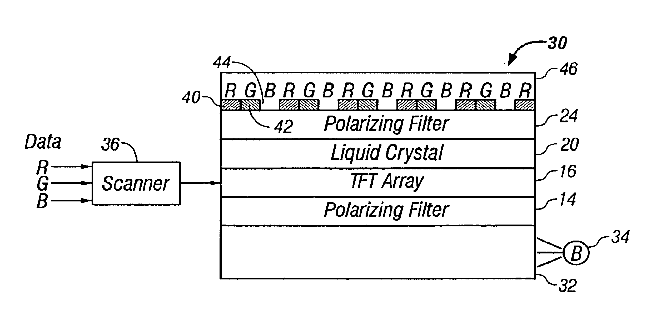
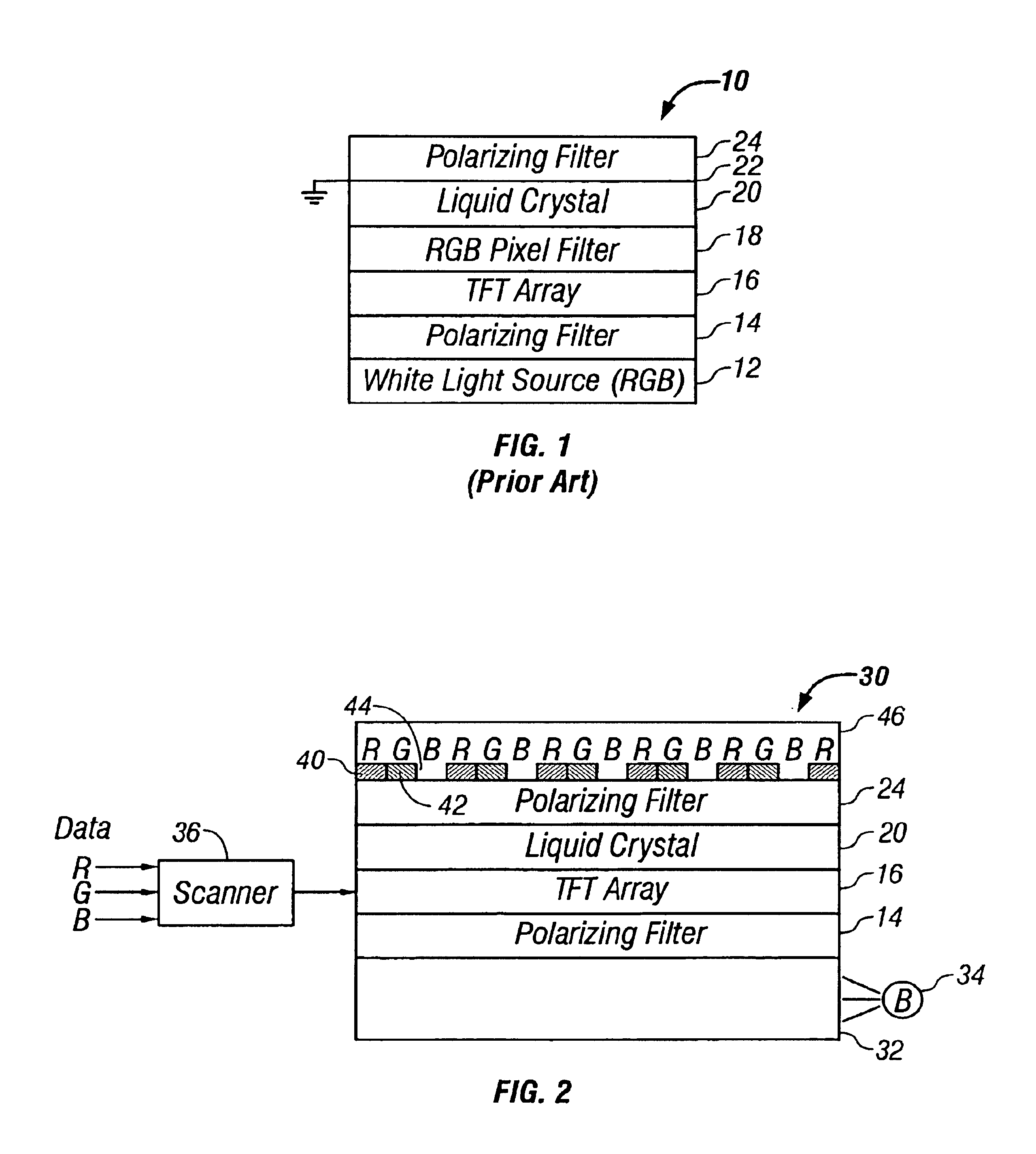
FIG. 2 is a cross-section of a portion of an LCD 30 in accordance with one embodiment of the invention. Other embodiments may include additional, well known features such as wavelength-dependent phase retarders and diffusers to increase the viewing angle.

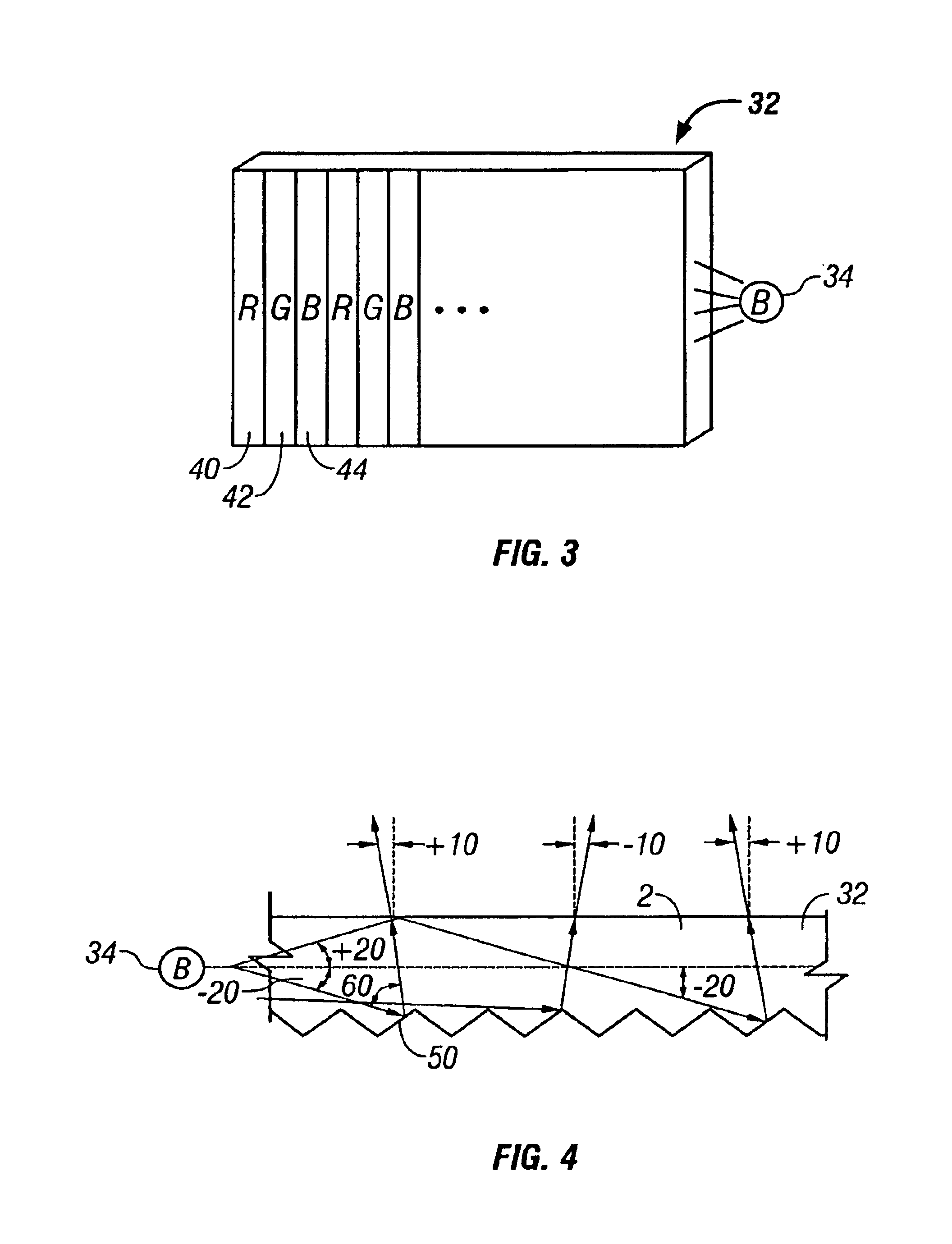
The LCD includes a light guide 32, which may be conventional. A blue light LED 34 is optically coupled to an edge of the light guide 32, and deformities are formed in or on a surface of the light guide 32 to leak out the blue light through the upper surface of the light guide 32. The light guide may also be a diffuser with the blue light source located behind the diffuser. Lenses may be formed on the top surface of the light guide 32 to collimate the light output from the light guide 32. Numerous types of well known light guides or defusers may be used to output the blue light. Preferably, the blue light output is non-Lambertian, forward collimated. In one embodiment, the blue light LED 34 outputs blue light with a wavelength of 460...


PUM

PropertyMeasurementUnit
wavelengthaaaaaaaaaa
quantum efficiencyaaaaaaaaaa
decay timeaaaaaaaaaa

Abstract

A color, transmissive LCD uses a backlight that supplies a uniform blue light to the back of the liquid crystal layer in an LCD. The blue light, after being modulated by the liquid crystal layer, is then incident on the back surface of phosphor material located above the liquid crystal layer. A first phosphor material, when irradiated with the blue light, generates red light for the red pixel areas of the display, and a second phosphor material, when irradiated with the blue light, generates green light for the green pixel areas of the display. No phosphor is deposited over the blue pixel areas.

Description

FIELD OF THE INVENTIONThis invention relates to color liquid crystal displays and, in particular, to a technique for backlighting a color liquid crystal display.BACKGROUNDLiquid crystal displays (LCDs) are commonly used in battery operated equipment, such as cell phones, personal digital assistants (PDAs), and laptop computers, and are replacing bulky CRTs as television screens and computer monitors. Presently, drawbacks of such LCDs include limited brightness, low efficiency, and limited viewing angle. LCDs can be monochrome or color and can be transmissive or reflective. The present invention deals with a color, transmissive LCD that uses backlighting.FIG. 1 is a cross-sectional view of a small portion of a prior art color, transmissive LCD. There are other types of color, transmissive LCD structures. The structure of FIG. 1 will be used to identify certain disadvantages of prior art LCDs that are avoided by the present invention.In FIG. 1, an LCD 10 includes a white light source ...

Claims


Application Information

Patent Timeline
Patent Type & Authority Patents(United States)
IPC IPC(8): G02F1/1335G02F1/13G02B5/30C09K11/56C09K11/62G02F1/13357G02F1/1368
CPCG02F1/133621G02F1/133617
Inventor MUELLER-MACH, REGINAMUELLER, GERD O.
Owner PHILIPS LUMILEDS LIGHTING CO LLC
Why Eureka
Try Eureka