Error proofing system for portable tools

a technology for detecting errors and portable tools, applied in anti-theft devices, program control, instruments, etc., can solve problems such as inability to use portable tools such as battery operated tools or tools, and achieve the effect of facilitating monitoring tools and enhancing the use of tools

Active Publication Date: 2005-01-18
ATLAS COPCO INDAL TECHN AB
View PDF78 Cites 232 Cited by
  • Summary
  • Abstract
  • Description
  • Claims
  • Application Information

AI Technical Summary

Benefits of technology

The present invention provides a system to enhance the use of tools that today have no way to provide substantial forms of error-proofing other than manual assurance. Through the addition of some intelligent electronics in the tool and a supervisory computer at the work cell, this invention provides a means for providing error-proofing operation and anti-theft capabilities. In addition, the present invention provides means for providing other capabilities to be included in a variety of equipment to facilitate monitoring the tools. Making some of the memory inside the tool available to the end user shall allow the end user to include select ed information to be part of the data transferred between the portable tool and the work cell controller that the end user deems pertinent for whatever additional information exchange needed to fulfill any additional tests, qualifications, or information exchange desired. This system and equipment enhances portable battery, electrical cord, hydraulic or compressed air powered tools to pro vide the requirements for them to be used in an error-proofed assembly line. In this regard, the system and equipment, for example, can assure that the correct tool make, model number, and configuration is to be used at a work cell, that the tool being used is properly calibrated to a preselected target value, that it is being cycled the proper number of times per part being assembled, and that the tool has been serviced or calibrated within required service intervals. Here such portable tools will be monitored and controlled remotely by R-F (radio frequency) communication and without the need for hard wire cable connections for such monitoring and control.

Problems solved by technology

However, this cannot be done with portable tools such as battery operated tools or tools electrically operated by a simple cord connection to an electrical outlet.

Method used


Image

  • Error proofing system for portable tools
  • Error proofing system for portable tools
  • Error proofing system for portable tools

Examples


Embodiment Construction

The following description of the preferred embodiment(s) is merely exemplary in nature and is in no way intended to limit the invention, its application, or uses.

The system has a number of different interacting components. These are generally shown in block diagram form in FIGS. 1-7.

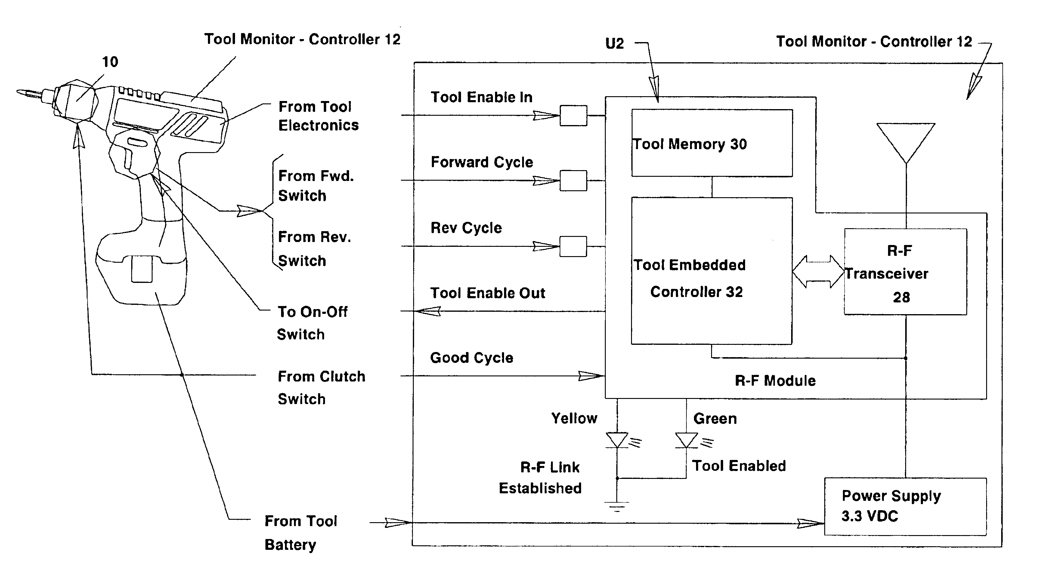
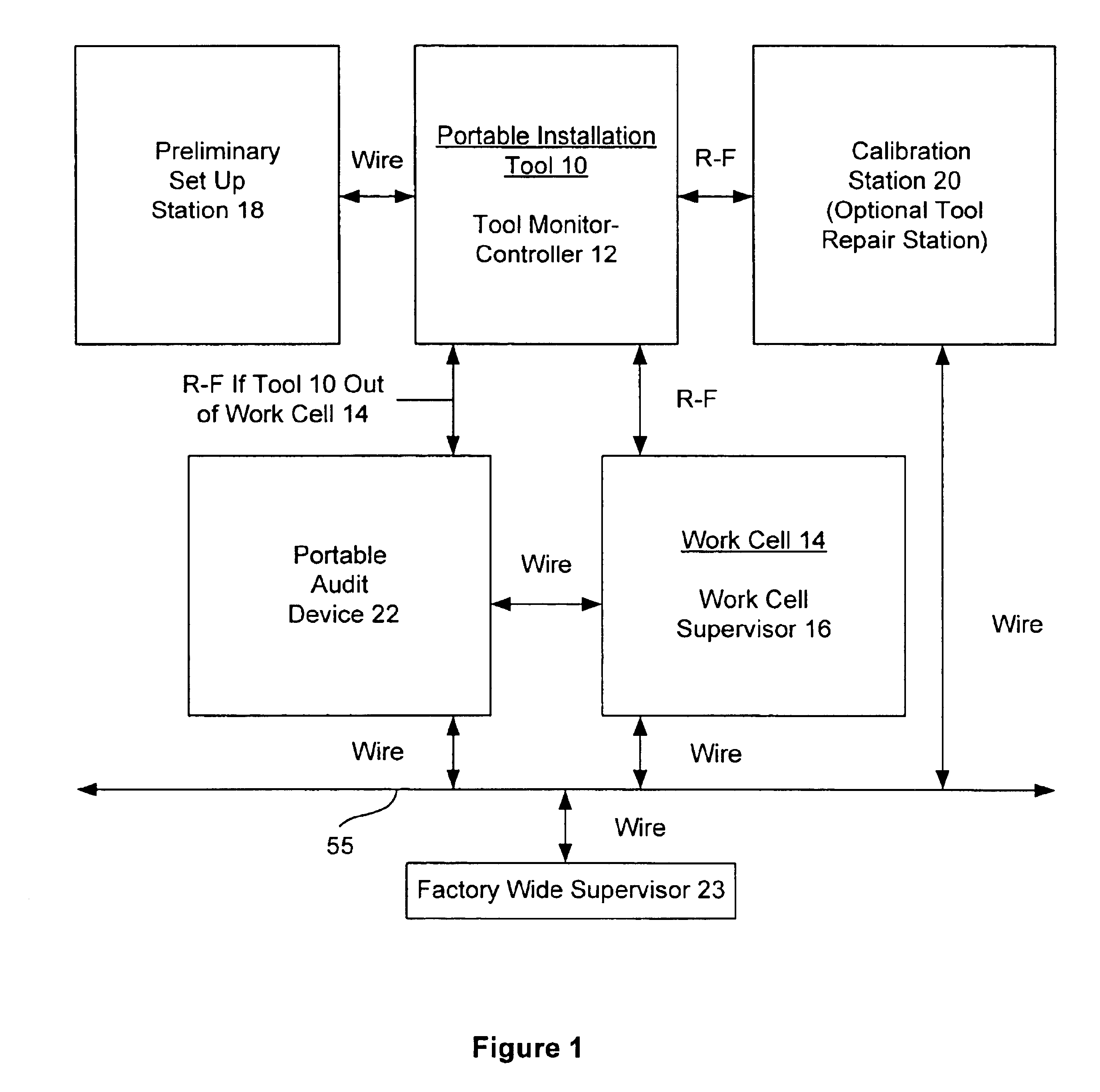
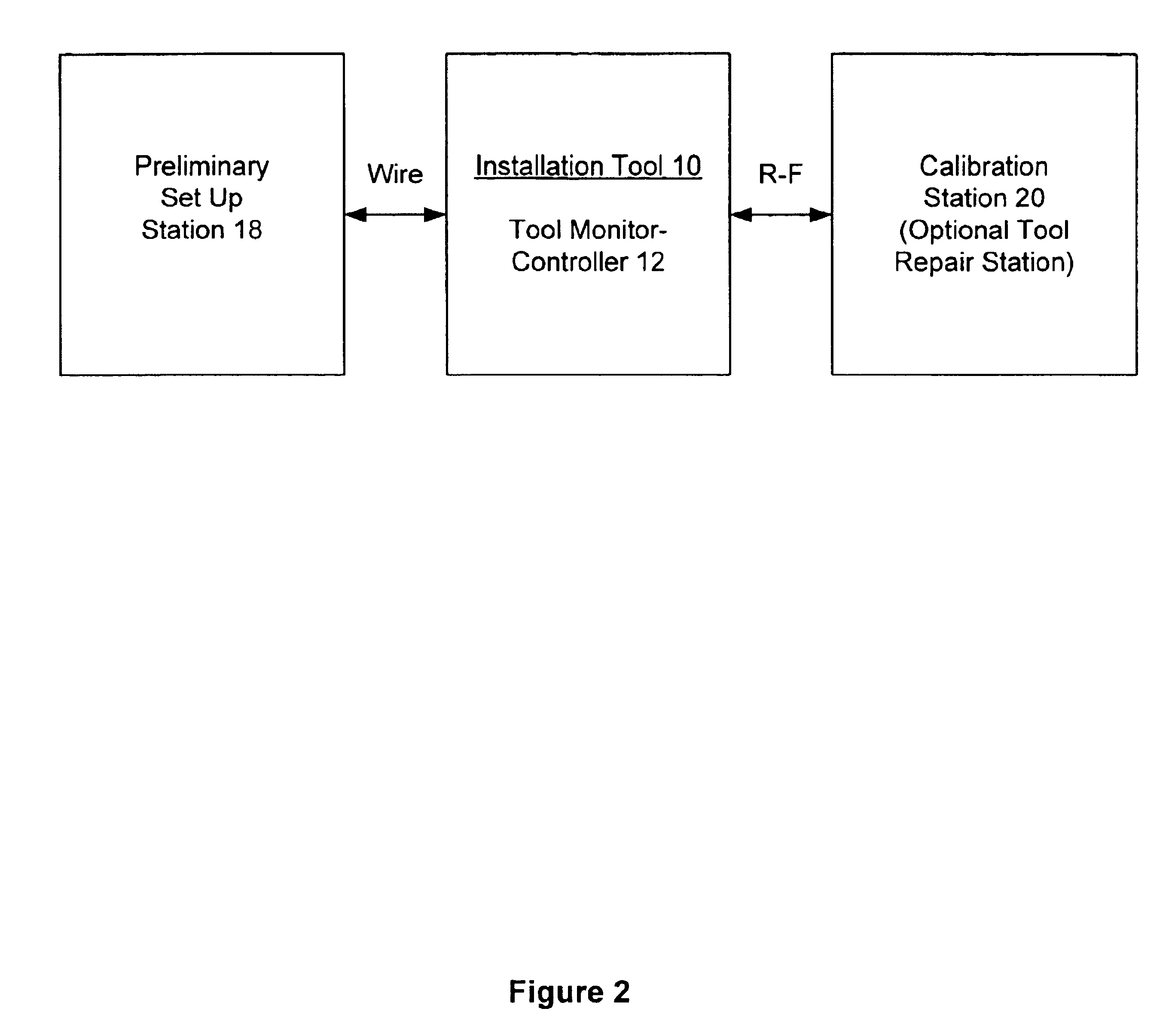
Looking now to FIG. 1, the portable self-powered installation tool 10 is provided with a tool monitor-controller 12, which, as will be seen, provides the necessary information for monitoring the tool 10 for the desired error-proofing operation. In this regard FIG. 1, generally shows the interconnection between the installation tool 10 and various components of the system which include a work cell supervisor (WCS) 16 at a particular work cell 14, a preliminary set up station 18, a calibration station 20 and a portable audit device 22 (PAD). In one form of the system, the work cell supervisor 16 and portable audit device 22 can be connected to a factory wide supervisor 23 for purposes to be seen.

The instal...


PUM


Abstract

A system for controlling and monitoring portable tools at a particular work cell remotely by R-F communication to provide error proofing of various parameters including that the correct tool is to be used at a work cell, the tool is properly calibrated for the operation to be performed, that it is being used a proper number of times per part being assembled or inspected, and that the tool has been calibrated within a selected service interval. The tools will be made actuable only by R-F communication with specific factory apparatus whereby theft of such portable tools will be inhibited.

Description

FIELD OF THE INVENTIONThe present invention relates to a system created to add assembly line error proofing and anti-theft features to existing portable tools. This invention greatly enhances the capabilities of a wide variety of tool types, but, for purposes of simplicity, the tool type exemplified in the body of this document shall be, by way of example, those used for installing threaded fasteners in assembling workpieces together.BACKGROUND OF THE INVENTIONMany assembly lines require some way to determine that the tools being used to perform assembly or operations requiring various parameters including predetermined magnitudes of torque, force, pressure, etc. at a particular work cell and are the correct make and model that have been properly set up, configured, calibrated and maintained. They then may require further error proofing to assure that the operations have been correctly performed by the technicians with the pre-approved tool that is used the proper number of times pe...

Claims


Application Information

Patent Timeline
Patent Type & Authority Patents(United States)
IPC IPC(8): G06F19/00G05B19/406
CPCG05B19/406G05B2219/33192G05B2219/50275G05B2219/49302G05B2219/45127Y10T70/5004
Inventor GILMORE, CURT D.RITCHEY, MICHAEL L.
Owner ATLAS COPCO INDAL TECHN AB
Why Eureka
Try Eureka