Electromagnetic flowmeter

a flowmeter and electromagnet technology, applied in the direction of mechanical measurement arrangements, mechanical roughness/irregularity measurements, instruments, etc., can solve the problems of increasing manufacturing cost and power consumption, increasing power consumption, and fluctuating measurement flow rate, etc., to achieve the effect of reducing nois

Inactive Publication Date: 2005-01-18
YAMATAKE HONEYWELL CO LTD
View PDF9 Cites 22 Cited by
  • Summary
  • Abstract
  • Description
  • Claims
  • Application Information

AI Technical Summary

Benefits of technology

It is an object of the present invention to provide an electromagnetic flowmeter which can realize flow rate measurement with precision increased to such an extent that no problem arises in terms of the influences of fluctuations and slurry noise caused by commercial power frequencies.
In order to achieve the above object, according to the present invention, there is provided an electromagnetic flowmeter comprising a coil which applies a magnetic field to a fluid flowing in a pipe line, exciting means for supplying an exciting current to the coil, noise eliminating means for eliminating noise from a measurement signal detected from the fluid under excitation by using a differential frequency component between a commercial power frequency and an exciting frequency, and arithmetic processing means for calculating a measurement flow rate on the basis of the measurement signal output from the noise eliminating means.

Problems solved by technology

When such a DC flow rate signal is loaded as a digital flow rate signal, fluctuations occur in a measurement flow rate due to the influences of the differential noise.
Such a conventional electromagnetic flowmeter, however, additionally requires an analog signal processing circuit for suppressing fluctuations caused by differential noise having the differential frequency between a commercial power frequency and a sampling frequency.
This leads to an increase in manufacturing cost and an increase in power consumption.
In a two-wire electromagnetic flowmeter in which the maximum current consumption is limited to 4 mA or less, in particular, an increase in power consumption poses a serious problem.
In this case, a filter circuit with a certain scale is required, and an increase in power consumption is inevitable.
As in the latter case, when commercial power noise as a noise source is to be attenuated, the electromagnetic flowmeter requires a subtraction circuit for accurately eliminating commercial power noise from electrode voltage in opposite phases, and an addition circuit for accurately extracting a commercial power frequency from commercial power noise, resulting in an increase in current consumption.

Method used


Image

  • Electromagnetic flowmeter
  • Electromagnetic flowmeter
  • Electromagnetic flowmeter

Examples


second embodiment

The second embodiment has exemplified the scheme of transmitting a signal and power sharing the same signal lines, i.e., the two-wire electromagnetic flowmeter. However, the present invention is not limited to this. The present invention can also be applied to a scheme of transmitting a signal and power through different lines, e.g., a four-wire electromagnetic flowmeter, to obtain the same effects as those described above.

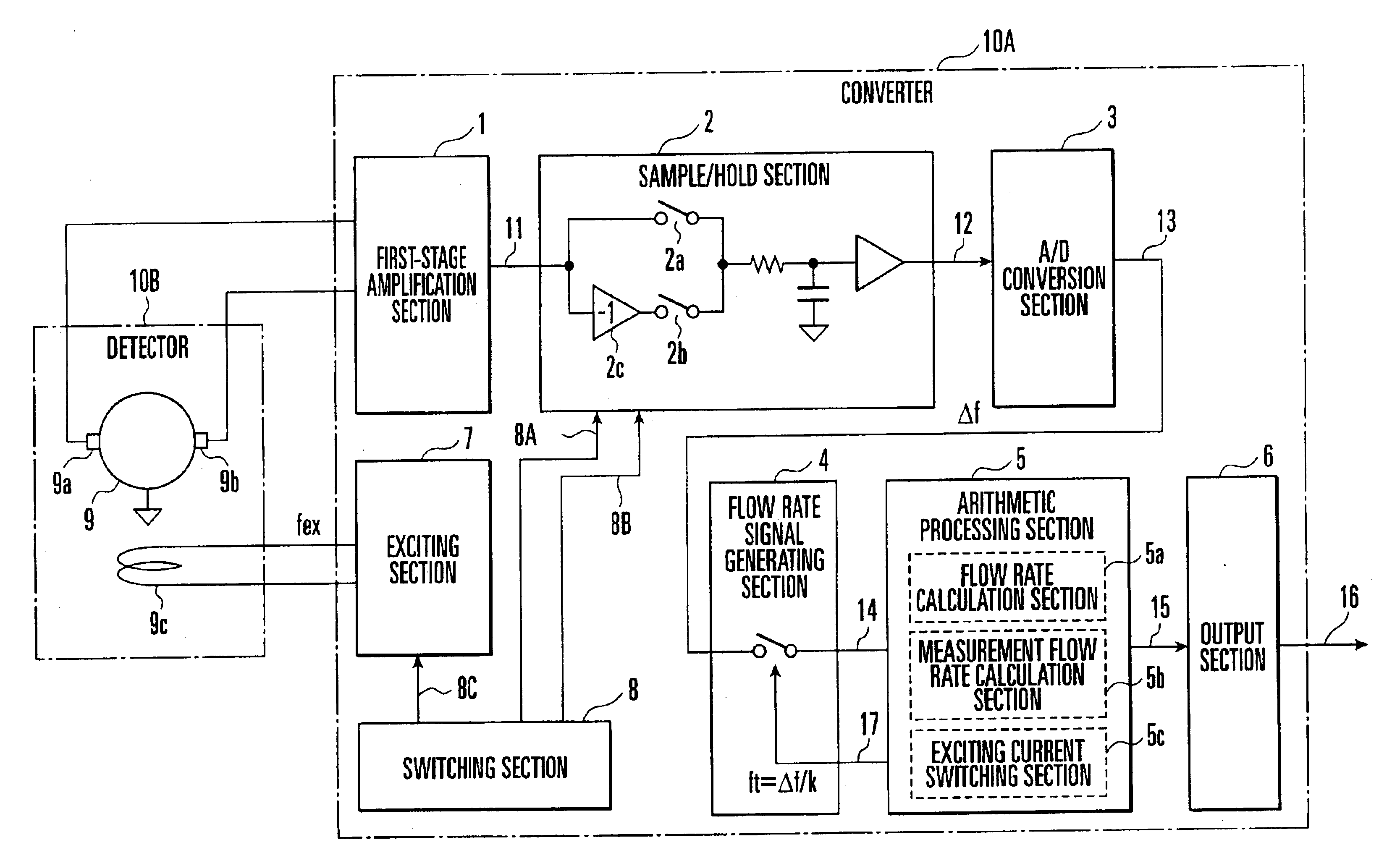
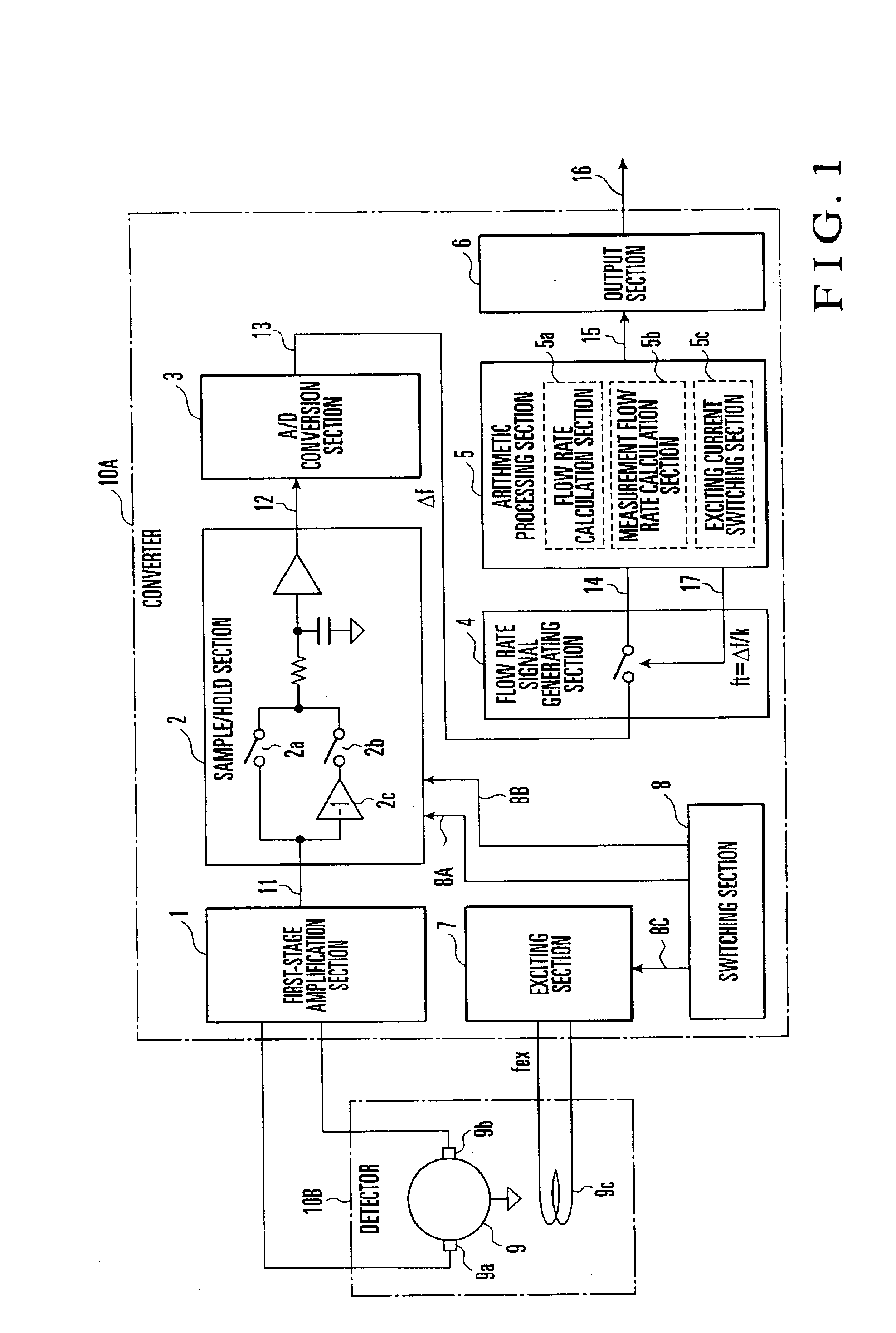
As has been described above, according to the present invention, a DC flow rate signal is loaded as a digital flow rate signal into the arithmetic processing section at a frequency corresponding to an integer submultiple of the differential frequency between an exciting frequency and the commercial power frequency of commercial power noise mixed in a fluid, thereby calculating a measurement flow rate. This eliminates the necessity to use any analog signal processing circuit and can efficiency suppress fluctuations in a measurement flow rate which are caused by dif...


PUM


Abstract

An electromagnetic flowmeter includes a coil, exciting section, noise eliminating section, and arithmetic processing section. The coil applies a magnetic field to a fluid flowing in a pipe line. The exciting section supplies an exciting current to the coil. The noise eliminating section eliminates noise from a measurement signal detected from the fluid under excitation by using a differential frequency component between a commercial power frequency and an exciting frequency. The arithmetic processing section calculates a measurement flow rate on the basis of the measurement signal output from the noise eliminating section.

Description

BACKGROUND OF THE INVENTIONThe present invention relates to an electromagnetic flowmeter and, more particularly, to an electromagnetic flowmeter having a function of suppressing fluctuations in measurement flow rate due to commercial power noise mixed in a fluid.When a fluid to be measured by an electromagnetic flowmeter passes through a pump or electromagnetic valve, 50-Hz / 60-Hz commercial power noise caused by such a device may be mixed in the fluid. If such commercial power noise is mixed in the fluid, since the commercial power noise is superimposed on the signal electromotive force obtained from the detector, differential noise having a differential frequency between the commercial power frequency and a sampling frequency is also superimposed on the DC flow rate signal obtained by sampling the signal electromotive force. When such a DC flow rate signal is loaded as a digital flow rate signal, fluctuations occur in a measurement flow rate due to the influences of the differentia...

Claims


Application Information

Patent Timeline
Patent Type & Authority Patents(United States)
IPC IPC(8): G01F1/56G01F1/60
CPCG01F1/60G01N2011/0066G01F15/065G01F15/068G01F1/58
Inventor OKUDA, KOUJISUZUKI, SHINMITSUTAKE, ICHIRO
Owner YAMATAKE HONEYWELL CO LTD
Why Eureka
Try Eureka