Joint assembly to resist galling

Inactive Publication Date: 2005-01-25
CATERPILLAR INC
View PDF21 Cites 32 Cited by
  • Summary
  • Abstract
  • Description
  • Claims
  • Application Information

AI Technical Summary

Benefits of technology

The present invention provides a joint assembly having an insert free floating positioned between two oscillating structures to reduce wear and galling the

Problems solved by technology

During use, the track joint assembly will receive loading and have a tendency to deflect and bend the track pin.
The deflection and bending of the track pin may result in edge loading and resulting stresses on the various track components as they move relative to one another.
The edge loading stresses have a tendency to wear or gall the var

Method used


Image

  • Joint assembly to resist galling
  • Joint assembly to resist galling
  • Joint assembly to resist galling

Examples


Embodiment Construction

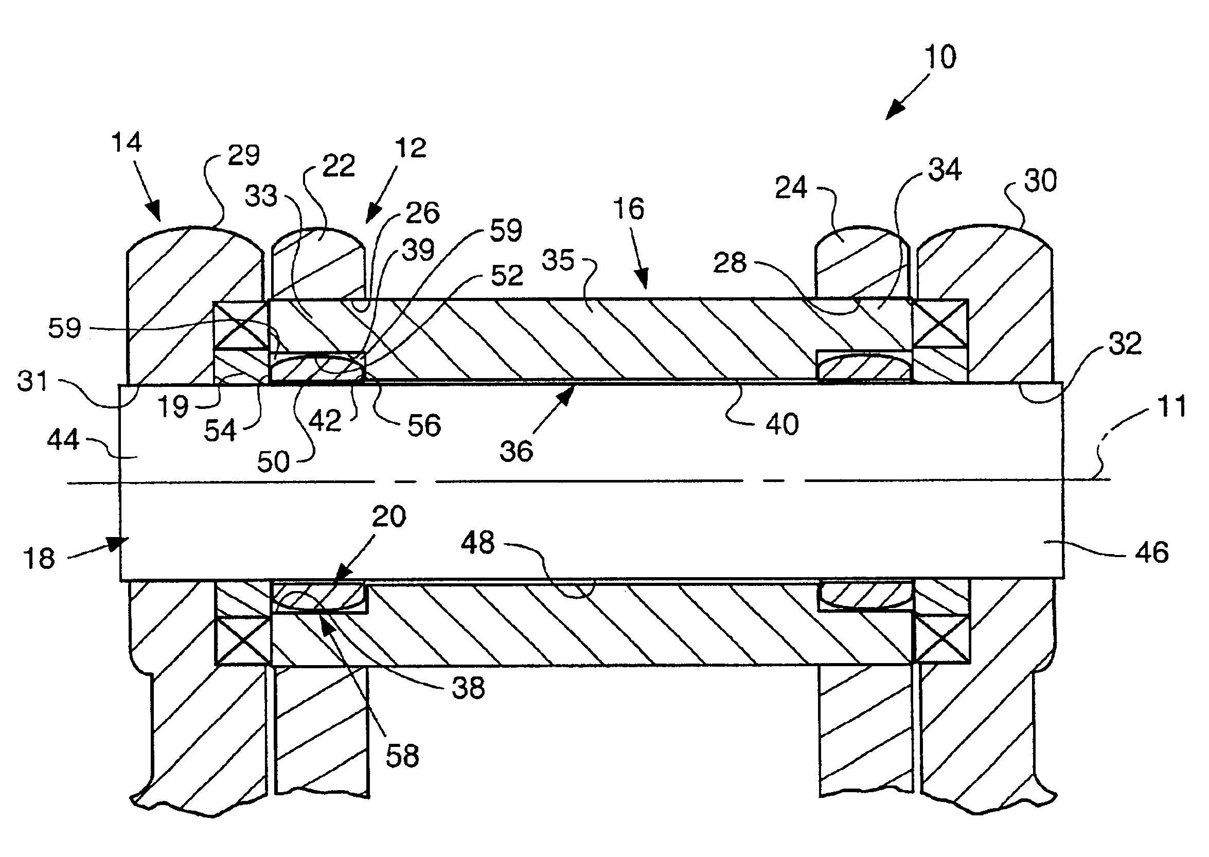
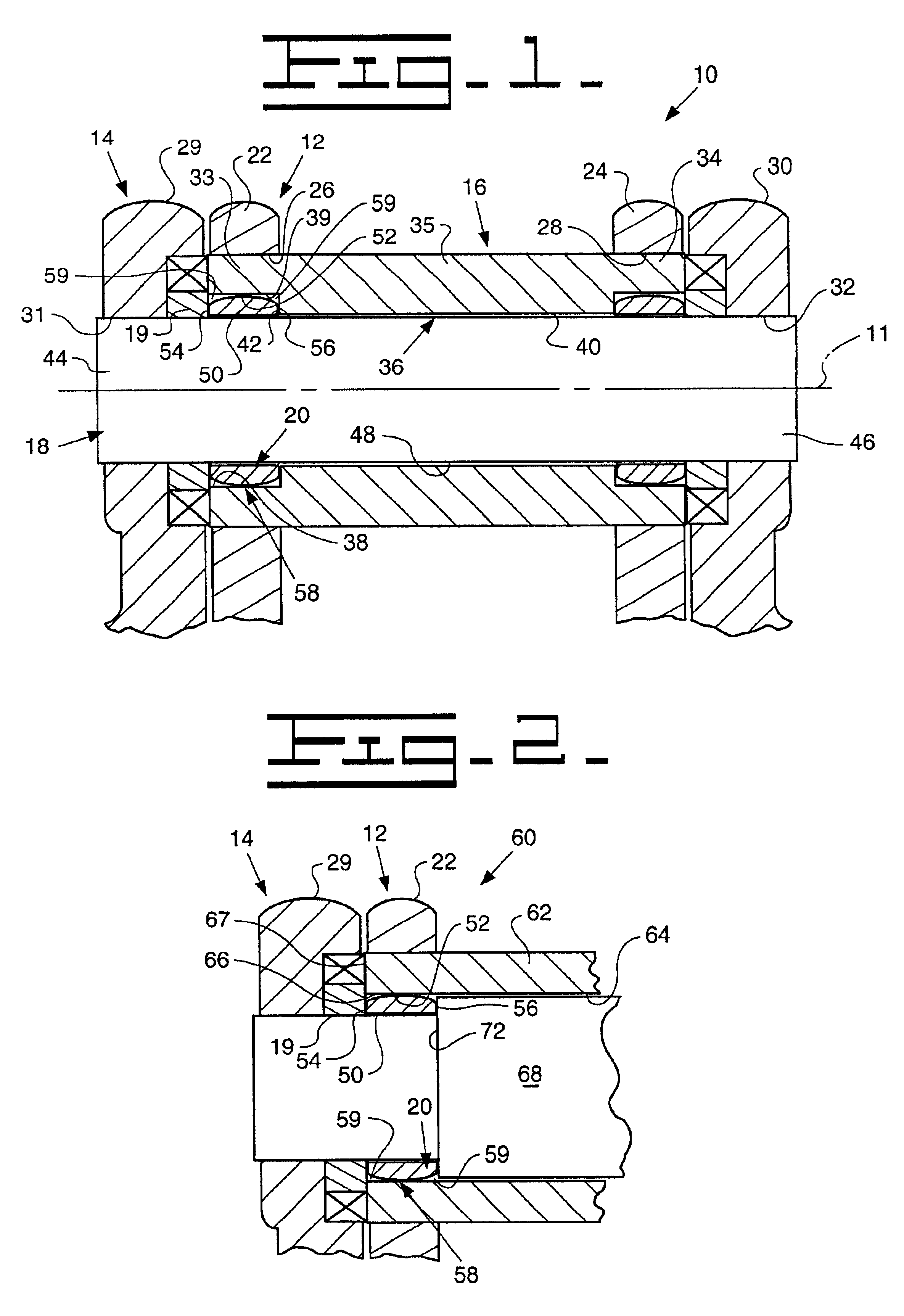
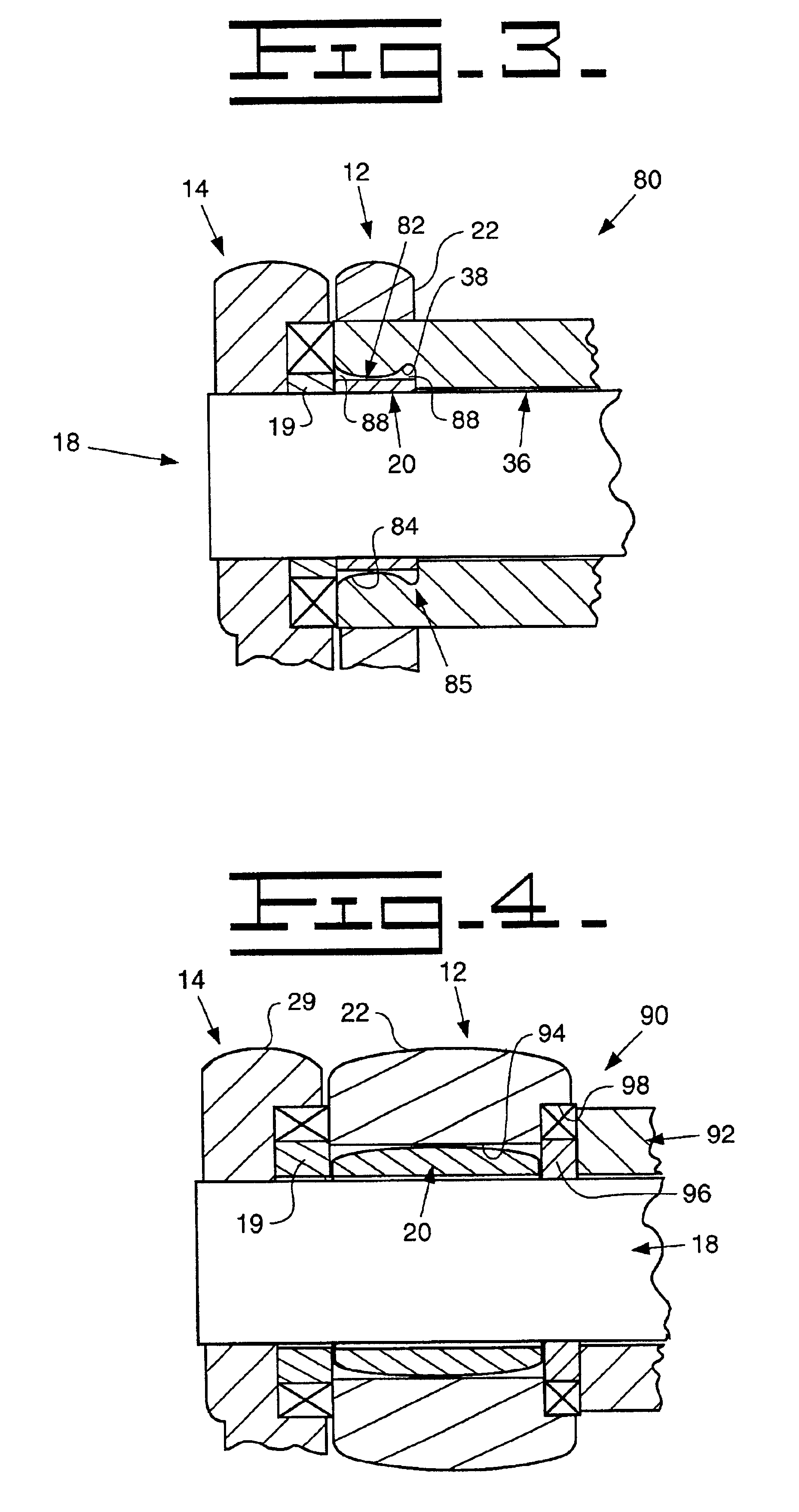
Referring to FIG. 1, a joint assembly 10 of the present invention is provided. The joint assembly 10 is used to connect a track chain (not shown) for use on a track type tractor (not shown) or similar tracked machine. The joint assembly 10 extends axially along an axis 11. The joint assembly 10 includes a first structure such as a first pair of spaced apart track links 12 and a second structure such as a second pair of spaced apart track links 14. A sleeve such as a track bushing 16 is positioned within the first structure 12. A track pin 18 is positioned within the second structure 14 and the track bushing 16. An insert 20, seen in detail in FIG. 7, is positioned between the track bushing 16 and the pin 18 and has a length L and thickness T. The track bushing 16, pin 18 and the insert 20 are made from any suitable material, such as steel. Referring specifically again to FIG. 1, a thrust ring 19 is positioned between the insert 20 and the second structure 14 to carry axial loads the...


PUM

PropertyMeasurementUnit
Angleaaaaaaaaaa
Lengthaaaaaaaaaa
Thicknessaaaaaaaaaa

Abstract

Joint assemblies are useful for connecting one structure to another structure. When the various structures deflect or bend, edge loading occurs therebetween. The subject joint assembly includes a pin positioned between a first and second structure. An insert is free floating positioned around the pin for contacting either of the first or second structures. A crown shaped surface is utilized on the insert at a substantially central location therealong. The crown shaped surface directs forces to the center of the insert to reduce edge loading.

Description

TECHNICAL FIELDThis invention relates to a joint assembly for connecting oscillating or rotating structures together, and more particularly, to an arrangement utilizing a crown shaped insert free-floating positioned between the structures to resist galling.BACKGROUND ARTJoint assemblies, such as a track joint, are customarily held together by a press or interference fit between the ends of a track pin and the respective bores of a track link. A track bushing may be used between the track pin and the track link. During use, the track joint assembly will receive loading and have a tendency to deflect and bend the track pin. The deflection and bending of the track pin may result in edge loading and resulting stresses on the various track components as they move relative to one another. The edge loading stresses have a tendency to wear or gall the various track components during contact with the deflected track pin. For this reason, it is well known to manufacture a portion of the track...

Claims


Application Information

Patent Timeline
IPC IPC(8): B21L9/00B21L9/08B62D55/15B62D55/14B62D55/21F16G13/02F16G13/06
CPCB21L9/08B62D55/15F16G13/06F16C11/045B62D55/21F16G15/12F16G13/02
Inventor BOTTOM, MICHAEL S.HOEFFT, THOMAS M.JENSEN, JEFF A.KUPFERSCHMID, JASON L.MATHEWSON, ERIC A.OERTLEY, THOMAS E.PLOUZEK, JOHN M.SHOOKMAN, DENNIS R.
Owner CATERPILLAR INC
Why Eureka
Try Eureka