Modular mounting arrangement and method for light emitting diodes

a technology of light emitting diodes and modules, applied in the direction of laminating printed circuit boards, instruments, lighting support devices, etc., can solve the problems of gas-filled tubes such as fluorescent or neon tubes, which are not typically long-lived, and require frequent replacemen

Inactive Publication Date: 2005-01-25
DIAMOND CREEK CAPITAL LLC
View PDF28 Cites 115 Cited by
  • Summary
  • Abstract
  • Description
  • Claims
  • Application Information

AI Technical Summary

Benefits of technology

For purposes of summarizing the present mounting arrangement and the advantages achieved over the prior art, certain advantages have been described herein above. Of course, it is to be understood that not necessarily all such advantages may be achieved in accordance with any particular embodime...

Problems solved by technology

Such bulbs typically do not have long operating lifetimes and thus require frequent replacement.
Gas-filled tubes, such as fluorescent or neon tubes, may have longer lifetimes, but operate using dangerously high voltages and are relatively expensive.
Further, both bulbs and gas-filled tubes consume substantial amounts ...

Method used


Image

  • Modular mounting arrangement and method for light emitting diodes
  • Modular mounting arrangement and method for light emitting diodes
  • Modular mounting arrangement and method for light emitting diodes

Examples


Embodiment Construction

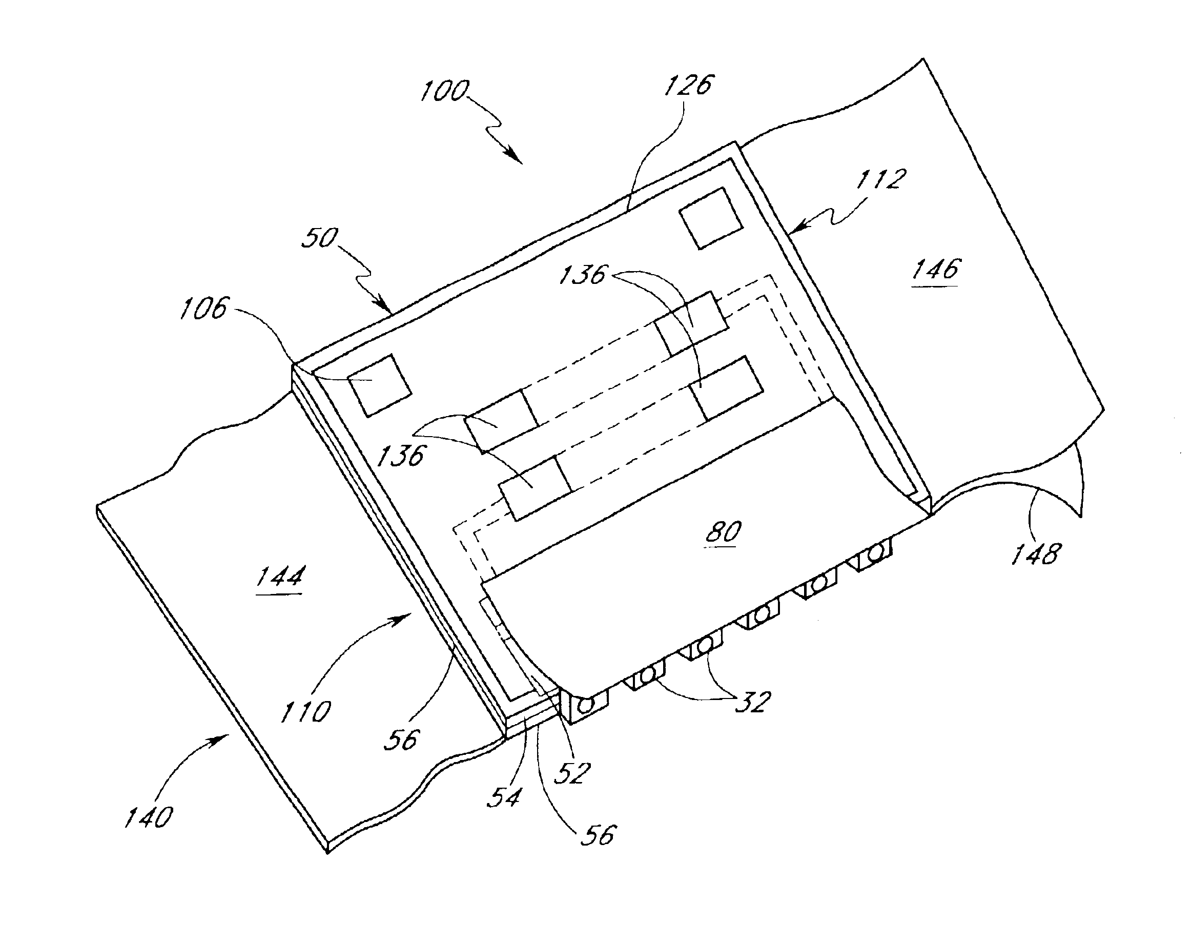
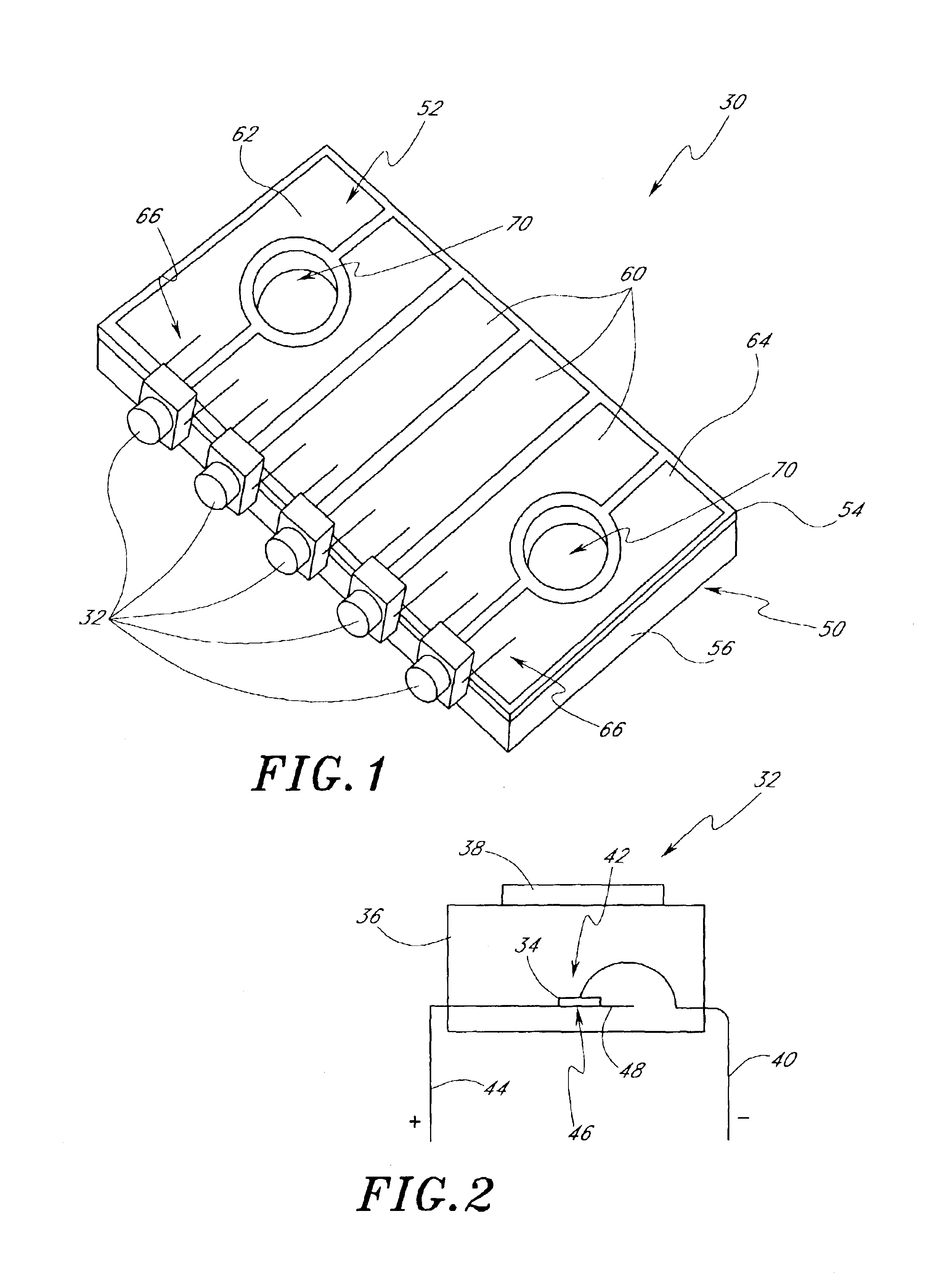
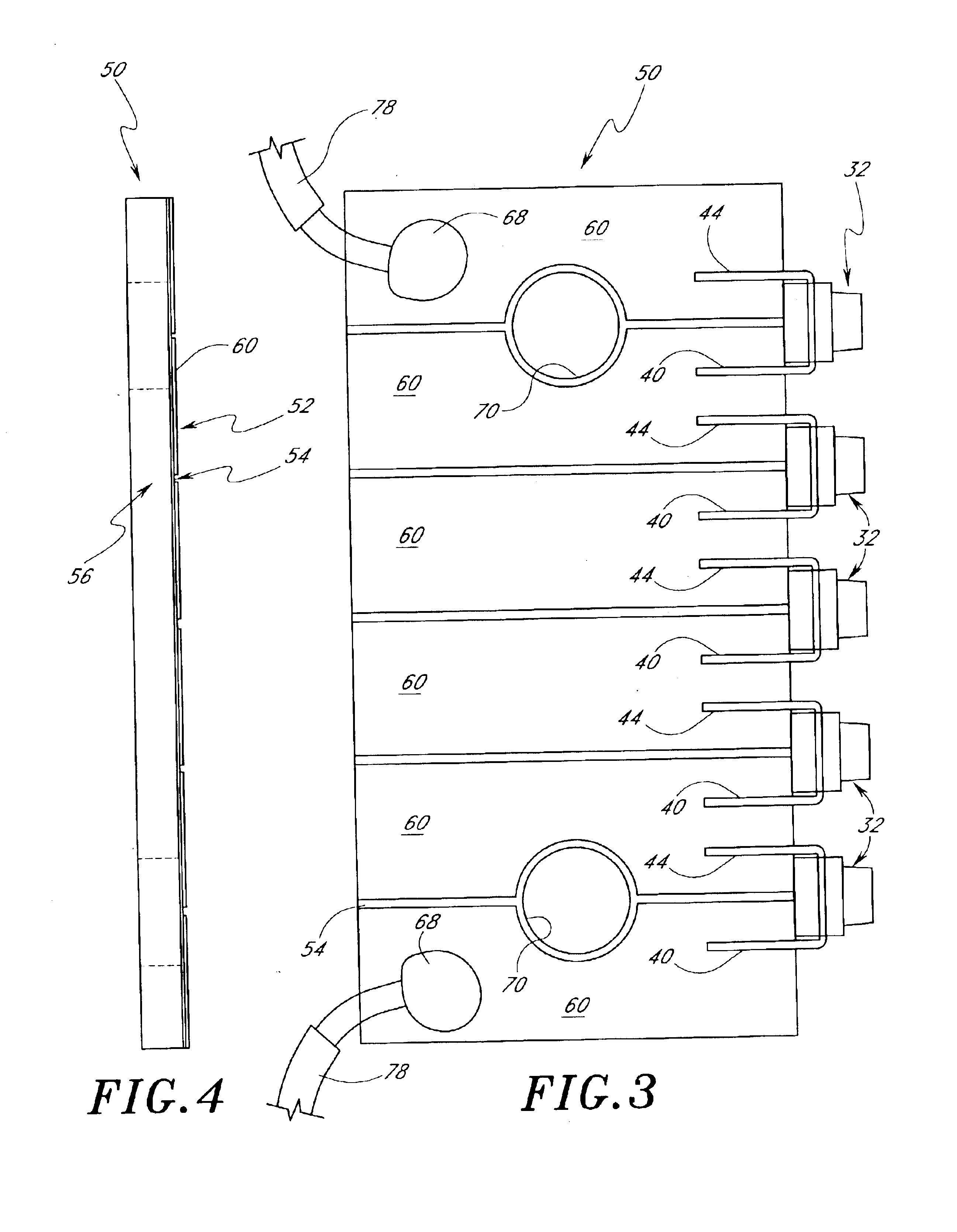
With reference first to FIG. 1, an embodiment of a light-emitting diode (LED) lighting module 30 is disclosed. In the illustrated embodiment, the LED module 30 includes five pre-packaged LEDs 32 arranged along a front edge of the module 30. It is to be understood, however, that LED modules can be constructed having any number of LEDs 32 mounted in any desired configuration.

With next reference to FIG. 2, a typical LED package 32 includes a diode chip 34 encased within a resin body 36. The LED package 32 typically has a focusing lens portion 38 on the body 36 and a pair of leads 40, 44, one of which is negative and the other positive. The negative lead 40 connects to an anode side 42 of the diode chip 34 and the positive lead 44 connects to a cathode side 46 of the diode chip 34. The positive lead 44 preferably includes a reflector portion 48 to help direct light from the diode 34 to the lens portion 38.

With next reference to FIGS. 1-5, the LED module 30 preferably comprises the five ...


PUM


Abstract

A modular light emitting diode (LED) mounting configuration is provided including a light source module having a plurality of pre-packaged LEDs arranged in a serial array. The module includes a heat conductive body portion adapted to conduct heat generated by the LEDs to an adjacent heat sink. A heat conductive adhesive tape connects the LED module to the mount surface. As a result, the LEDs are able to be operated with a higher current than normally allowed. Thus, brightness and performance of the LEDs is increased without decreasing the life expectancy of the LEDs. A plurality of such LED modules can be pre-wired together in a substantially continuous fashion and provided in a dispenser, such as a roll or box. Thus, to install a plurality of such LED modules, a worker simply pulls modules from the dispenser as needed, secures the appropriate number of modules in place, and connects the assembled modules to a power source.

Description

BACKGROUND OF THE INVENTION1. Field of the InventionThe present invention relates generally to light emitting diode (LED) lighting devices and more particularly to LED lighting modules having heat transfer properties that improve the efficiency and performance of LEDs.2. Description of the Related ArtMost lighting applications utilize incandescent or gas-filled bulbs, particularly lighting applications that require more than a low level of illumination. Such bulbs typically do not have long operating lifetimes and thus require frequent replacement. Gas-filled tubes, such as fluorescent or neon tubes, may have longer lifetimes, but operate using dangerously high voltages and are relatively expensive. Further, both bulbs and gas-filled tubes consume substantial amounts of power.In contrast, light emitting diodes (LEDs) are relatively inexpensive, operate at low voltage, and have long operating lifetimes. Additionally, LEDs consume relatively little power and are relatively compact. Th...

Claims


Application Information

Patent Timeline
IPC IPC(8): H05K1/02F21V29/00F21S4/00H01L25/10H01L25/13H01L33/00H05K1/05F21V17/00H01L33/64
CPCG09F13/0404G09F13/22H05K1/0203F21S4/003F21V29/004F21Y2101/02H01L25/13H01L33/64H01L33/647H05K1/056H05K3/0058H05K2201/10106H05K2201/10446Y10S362/80H01L2224/48091H01L2224/48137H01L2224/48247F21V17/007H01L2924/00014F21S4/20F21Y2115/10F21V29/70
Inventor SWARIS, JAGATHVAN NESS, SCOTT
Owner DIAMOND CREEK CAPITAL LLC
Why Eureka
Try Eureka