
Optical transmitter-receiver module, method of manufacturing the module, and electronic device using the module

a technology of optical transmitter and receiver, which is applied in the direction of optical elements, instruments, and semiconductor/solid-state device details, etc., can solve the problems of inconvenient user, damage to the end surface of optical fiber b>1102/b> and/or the partition plate b>1111/b>

Inactive Publication Date: 2005-01-25
MICROSOFT TECH LICENSING LLC
View PDF12 Cites 1 Cited by
  • Summary
  • Abstract
  • Description
  • Claims
  • Application Information

AI Technical Summary

Benefits of technology

[0009]Accordingly, an object of this invention is to provide an optical transmitter-receiver module and an electronic device using the same, which module is able to perform high-quality optical transmission by full-duplex communication scheme by using a light-tight partition plate and able to prevent the optical fiber end surface and the partition plate from being damaged even if the inserted optical plug is rotated in the module.
[0010]Another object of the present invention is to provide a method of easily manufacturing such modules.

Problems solved by technology

Therefore, the optical plug 1030 cannot be inserted into the optical transmitter-receiver module unless the key 1031 is aligned with the keyway of the optical transmitter-receiver module when fitting the optical plug 1030, and this disadvantageously causes inconvenience to the user.
Therefore, similarly to the first conventional optical transmitter-receiver module, there occurs a problem that the end surface of the optical fiber 1102 and / or the partition plate 1111 is damaged.

Method used


Image

  • Optical transmitter-receiver module, method of manufacturing the module, and electronic device using the module
  • Optical transmitter-receiver module, method of manufacturing the module, and electronic device using the module
  • Optical transmitter-receiver module, method of manufacturing the module, and electronic device using the module

Examples


Embodiment Construction

om the right-hand side;

[0074]FIG. 28 is a sectional view taken along line XXVIII—XXVIII of FIG. 26;

[0075]FIG. 29 is a side view of an optical cable;

[0076]FIG. 30 is a sectional view showing a state in which the front end of an optical plug is fit in a hole of an engagement portion of the partition plate unit;

[0077]FIG. 31 is a sectional view of an optical transmitter-receiver module in which an optical plug is inserted in a jack section;

[0078]FIG. 32A is a plan view of a light-emitting element drive circuit board, and FIG. 32B is a plan view of a light-receiving element amplification electric circuit board;

[0079]FIG. 33 is a block diagram schematically showing an optical transmitter-receiver system in which the optical transmitter-receiver module of this invention is employed;

[0080]FIG. 34 is a block diagram schematically showing another optical transmitter-receiver system in which the optical transmitter-receiver module of this invention is employed;

[0081]FIG. 35A is a plan view of...


PUM


Abstract

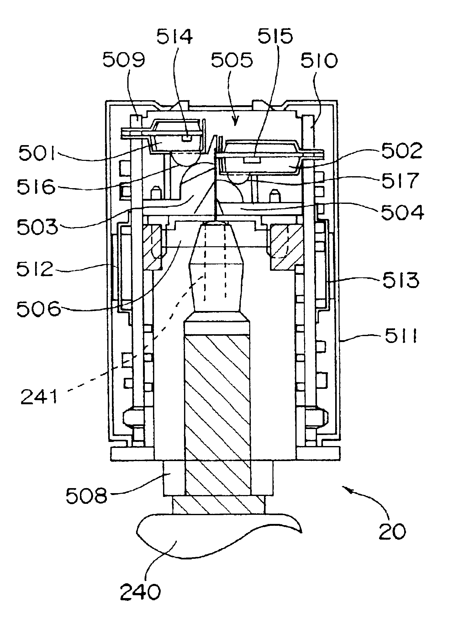
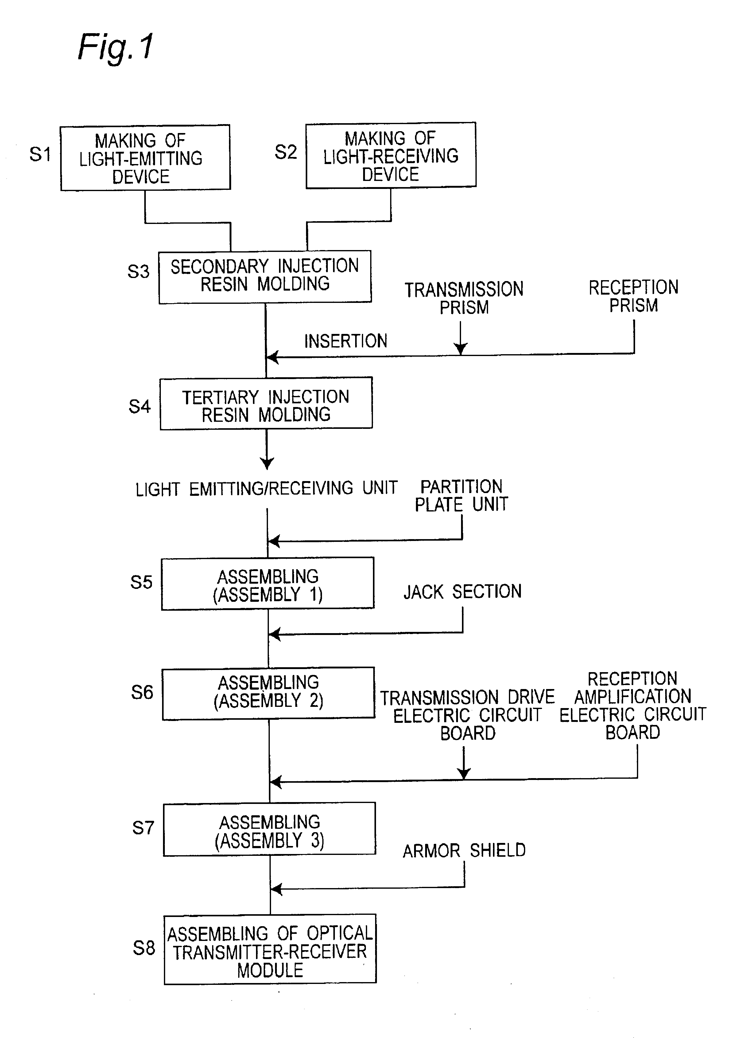
In an optical transmitter-receiver module for performing optical transmission and reception by using a single-core optical fiber, a light-tight partition plate unit 506 for separation between an optical path of a transmission signal light and an optical path of a reception signal light is held between a jack section 508 for detachably holding an optical plug 240 and a light emitting / receiving unit 505 having an LED 514 and a PD 515 positioned and fixed in place and molded in one piece.

Description

BACKGROUND OF THE INVENTION[0002]The present invention relates to an optical transmitter-receiver module and an electronic device for use in a single-core bidirectional optical transmitter-receiver system capable of performing transmission and reception with a single-core optical fiber. The present invention relates, in particular, to a digital communication system, which is able to perform high-speed transmission, such as IEEE1394 (Institute of Electrical and Electronic Engineers 1394) and USB (Universal Serial Bus) 2.0. The present invention also relates to a method of manufacturing the optical transmitter-receiver module.[0003]Conventionally, as a first optical transmitter-receiver module, there is a one as described in Japanese Patent Laid-Open Publication No. 2001-116961. In this optical transmitter-receiver module, full-duplex communications are achieved by reducing electric crosstalk by employing a shield plate while reducing optical crosstalk by employing a light-tight parti...

Claims


Application Information

Patent Timeline
Patent Type & Authority Patents(United States)
IPC IPC(8): G02B6/42G02B6/43H01L23/48H01L31/0232H01L31/12H01L33/00H01L33/58
CPCG02B6/4204G02B6/4219G02B6/4246G02B6/43H01L2224/45144H01L2224/49171H01L2924/3025H01L2224/48247H01L2924/00H01L2924/181H01L2924/00012
Inventor OHE, NOBUYUKINAGURA, KAZUHITOSONE, MOTOKI
Owner MICROSOFT TECH LICENSING LLC
Learn More