
Multi-chambered, compliant apparatus for restraining workpiece and applying variable pressure thereto during lapping to improve flatness characteristics of workpiece

a technology of flatness control and workpiece, applied in the direction of grinding machine components, manufacturing tools, lapping machines, etc., can solve the problems of parts that distort and/or elastically deform, elastically distort parts, etc., to improve the height range of read sensor strips, improve the lapping of rows, and excellent flatness characteristics

Inactive Publication Date: 2005-01-25
WESTERN DIGITAL TECH INC
View PDF29 Cites 9 Cited by
  • Summary
  • Abstract
  • Description
  • Claims
  • Application Information

AI Technical Summary

Benefits of technology

One embodiment of an apparatus and method of the present invention improves the lapping of rows of magnetic recording heads by providing excellent flatness characteristics, such as crown, camber, twist, recession, and protrusion, while also improving the read sensor stripe height range. The present invention provides a lapping structure that has improved kinematics for flatness and resistance feedback for better stripe height control.
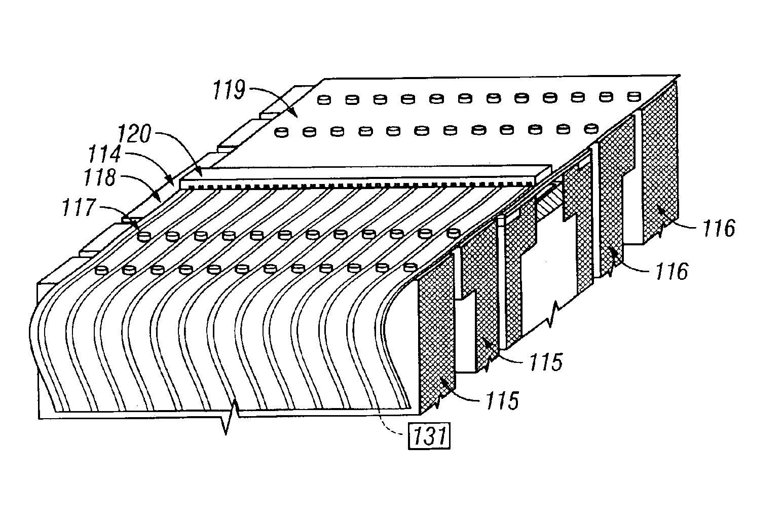
It is desirable to be able to vary the amount or removal of material such that the final stripe height of the row of recording heads has a narrower range. The higher vertical forces result in greater lap rates, and this is accomplished by adjusting the pressure in the chambers such that higher pressure is applied to those heads with higher stripe height. Conversely, relatively lower pressure is applied to recording heads with lower stripe height. To set or adjust the pressures in the chambers, measurements of the read sensor resistance are taken to calculate the stripe height. These calculations are based on knowing the sensor width, thickness, and contact geometry. The stripe height is roughly proportional to the reciprocal of resistance. Increasing the number of chambers increases the degrees of freedom to which the system can vary the stripe height removal. The methods of adjusting the pressures in the chambers for variable amounts of stripe height removal can be either through sampled resistance measurement or in-situation sampled measurement of resistance.

Problems solved by technology

Any variance in the restraining forces will cause the parts to distort and / or elastically deform upon removal of the forces.
Unfortunately, this combination of forces elastically distorts the part (e.g., the head).

Method used


Image

  • Multi-chambered, compliant apparatus for restraining workpiece and applying variable pressure thereto during lapping to improve flatness characteristics of workpiece
  • Multi-chambered, compliant apparatus for restraining workpiece and applying variable pressure thereto during lapping to improve flatness characteristics of workpiece
  • Multi-chambered, compliant apparatus for restraining workpiece and applying variable pressure thereto during lapping to improve flatness characteristics of workpiece

Examples


Embodiment Construction

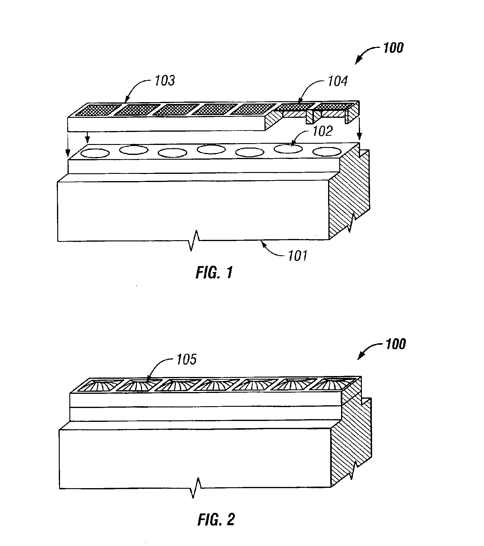
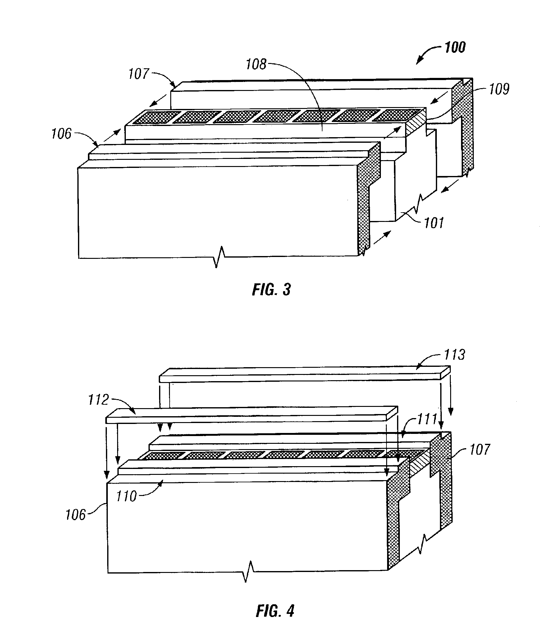
Referring to FIG. 1, one embodiment of a lapping fixture 100 constructed in accordance with the present invention is shown. Lapping fixture 100 is inverted from its position for normal operation to reveal details of the invention. Lapping fixture 100 comprises a rigid base 101 that is formed from a material such as aluminum. Base 101 has a plurality of individual ports 102 which extend therethrough to form, in the embodiment shown, a single row array. An air bank fixture 103 having a plurality of respective air cells, including flexible membranes 104, is joined to base 101 over ports 102. Fixture 103 and membranes 104 are preferably formed or molded from the same elastic material, such as molded polyurethane, and are adhesively bonded to fixture 101 such that ports 102 are sealed at one end. The air cells in fixture 103 have thick wall sections in all walls except pressure membranes 104. The thin membranes 104 allow the air pressure through ports 102 to be directed to and displace t...


PUM

PropertyMeasurementUnit
heightaaaaaaaaaa
flexibleaaaaaaaaaa
pressureaaaaaaaaaa

Abstract

An apparatus and method of lapping of rows of magnetic recording heads uses multiple fluid-filled ports with variable pressure against a flexible adhesive tape to secure to and support the row. The tape provides the necessary tangential restraining force to drag the workpiece along a lapping plate. The multiple ports beneath the tape provide the necessary normal force to press the workpiece against the lapping plate to allow lapping to occur. The amount of material removal from the row is varied by adjusting the pressure in the ports such that higher pressure is applied to those heads with higher stripe height, and lower pressure is applied to recording heads with lower stripe height. To set or adjust the port pressures, measurements of the read sensor resistance are taken to calculate the stripe height. The stripe height is roughly proportional to the reciprocal of resistance.

Description

BACKGROUND OF THE INVENTION1. Technical FieldThe present invention relates in general to a fixture for restraining workpieces during fabrication and, in particular, to improving the flatness control of a workpiece during a lapping process. Still more particularly, the present invention relates to a compliant apparatus for restraining a workpiece having improved kinematics for flatness and electrical resistance feedback for better stripe height control.2. Description of the Related ArtData access and storage devices (DASDs) such as disk drives use magnetic recording heads to read data from or write data to the disks as they spin inside the drive. Each head has a polished air bearing surface (ABS) with flatness parameters, such as crown, camber, and twist. The ABS allows the head to “fly” above the surface of its respective spinning disk. In order to achieve the desired fly height, fly height variance, take-off speed, and other aerodynamic characteristics, the flatness parameters of t...

Claims


Application Information

Patent Timeline
Patent Type & Authority Patents(United States)
IPC IPC(8): B24B21/04B24B37/04B24B49/16B24B37/16
CPCB24B21/04B24B49/16B24B37/16B24B37/048
Inventor CHURCH, MARK A.DESOUCHES, ALAIN M. L.GEE, GLENN P.
Owner WESTERN DIGITAL TECH INC
Learn More