Closing device for flexible tubular packaging

a tubular packaging and sealing device technology, applied in packaging, sausage skin tying apparatus, butchering, etc., can solve the problem that the punch is not integrated in the constricting unit, and achieve the effect of reducing the consumption of propellant agent, small overall unit thickness, and reducing wear and tear

Inactive Publication Date: 2005-01-25
POLY CLIP SYST
View PDF4 Cites 9 Cited by
  • Summary
  • Abstract
  • Description
  • Claims
  • Application Information

AI Technical Summary

Benefits of technology

The short advance path means not only correspondingly little wear and tear, but above all also reduced consumption of the propellant agent for the punch closure motion. The advantage of a short-stroke closure cylinder in particular in connection with a stationary closure clip magazine, which does not swivel along with the punch and its guidance when the cylinder swivels, is known from the older patent application 199 53 694.5. But there the punch is not integrated in the constricting unit.
In a beneficial embodiment, the arrangement of a constricting unit consists of three constricting components, which in each case are seated on one end on a circle concentric to the axis of the packaging tube offset by 120°, in such a way that one of the constricting components consists of a plate and carries the matrix, one consists of two plane-parallel sheets of metal with a distance that exceeds the thickness of the plate slightly, and the third constricting component consists in part of a plate, in part of two plane-parallel sheets of metal of that design, wherein the partitioning runs in the middle between the two ends of this constricting component and radially to the bearing circle (in the opening state). In this way, both the matrix and the punch guidance have stable carriers available which, however, can slide between the metal sheets of the respectively other constricting components with their sections no longer exposed during constriction, and in this way obtain a small thickness of the overall unit.

Problems solved by technology

But there the punch is not integrated in the constricting unit.

Method used


Image

  • Closing device for flexible tubular packaging
  • Closing device for flexible tubular packaging
  • Closing device for flexible tubular packaging

Examples


Embodiment Construction

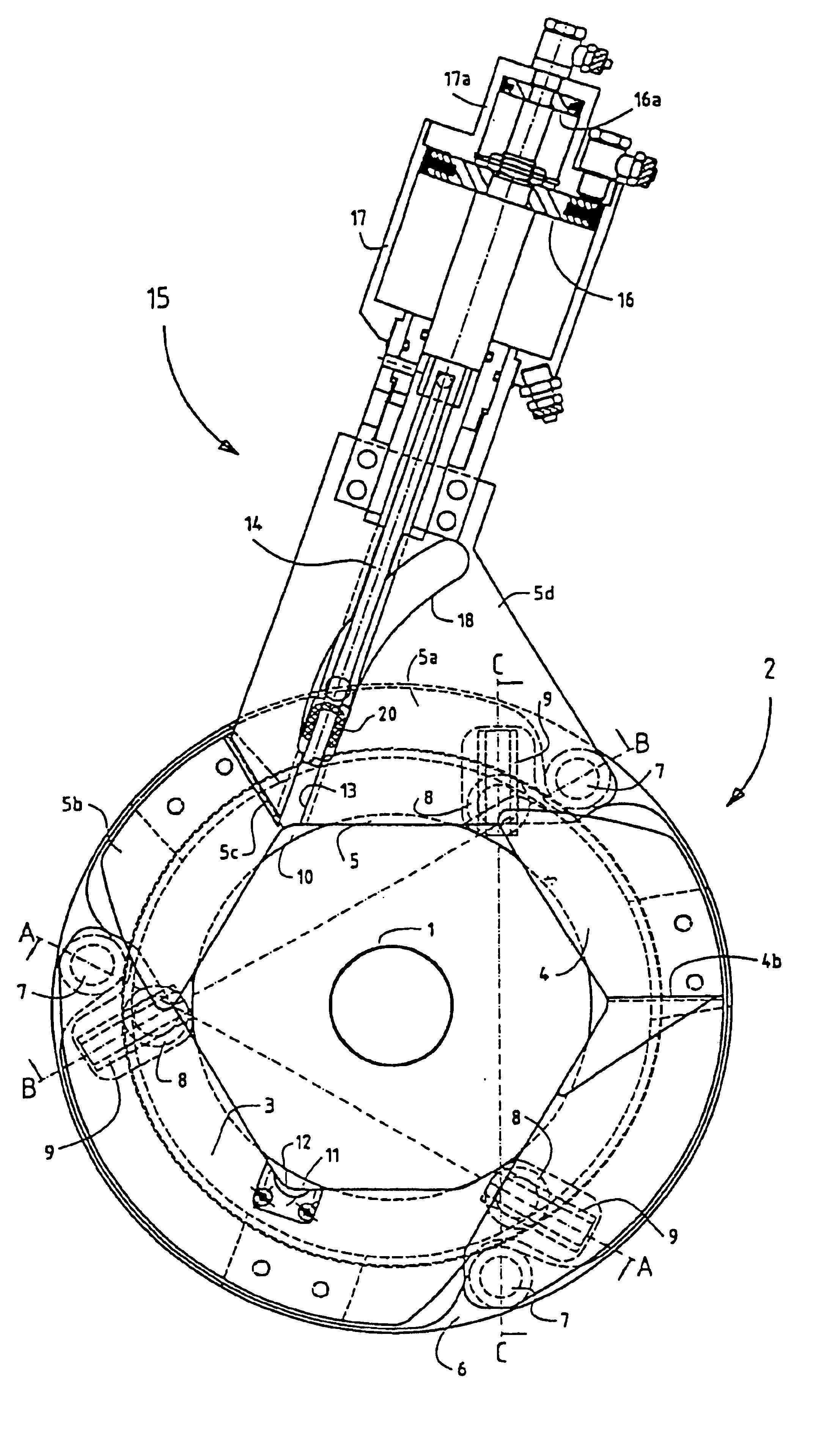
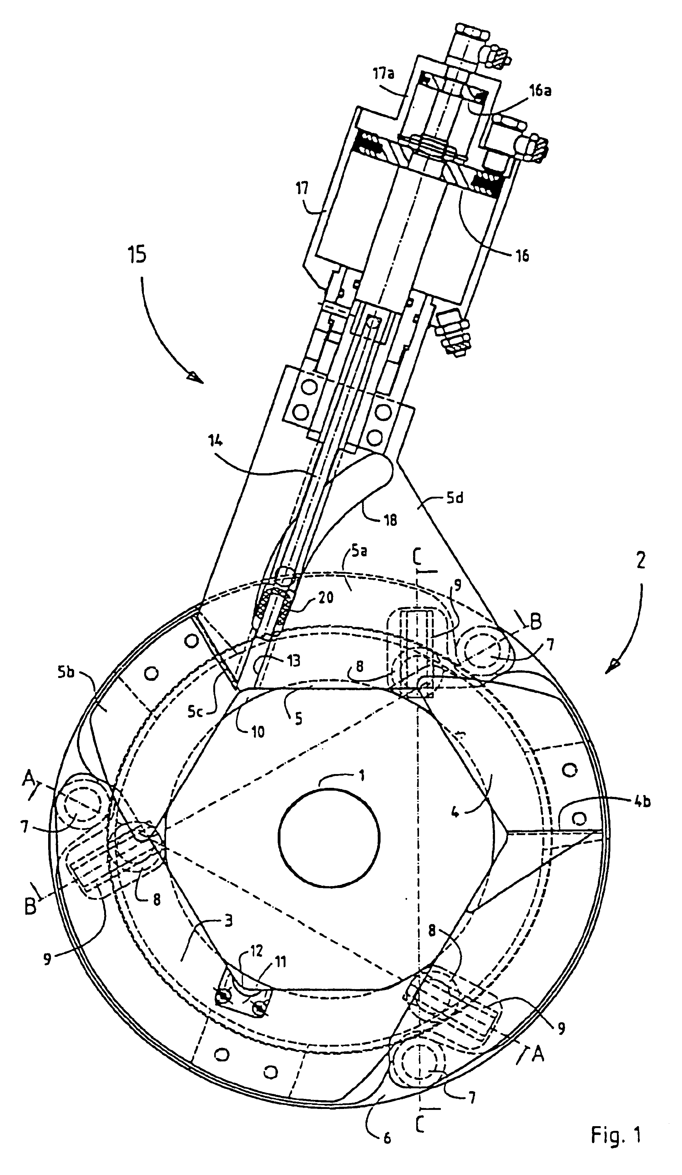
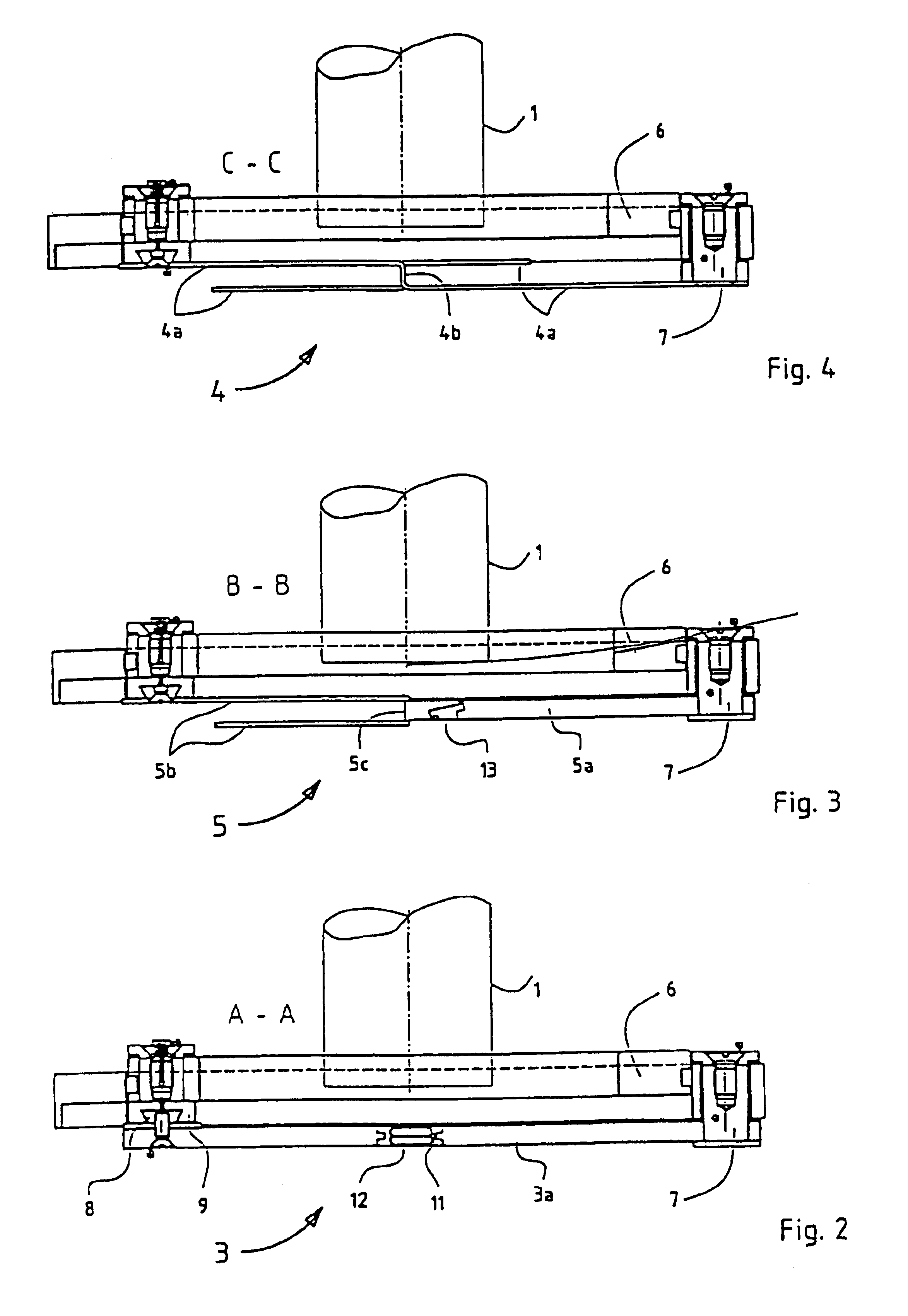
The constricting unit of the closing apparatus of the invention, designated as 2 in general, is arranged concentrically to the aperture of a stuffing tube 1, which is only indicated, (added in FIGS. 2-4). It basically consists of three plate-shaped constricting components 3, 4 and 5, which are seated with one of their ends in a swiveling manner on a stationary carrier ring 6 on pins 7—in each case mutually offset by 120°. The other ends of the constricting components 3, 4 and 5 each are seated with sliding blocks 8 in links 9 on a concentrically interior ring 10 in such a way that its rotation leads to a swiveling of the constricting arms and thus their closure, so that a packaging tube located in the opening is gathered into a braid (FIGS. 6 and 7). In addition, refer to DE-PS 199 34 154.

The operating areas of all constricting components 3, 4 and 5 therefore have a (rounded-off) bend of 120° in the center between their ends so that in the open state of the constricting unit the cir...


PUM


Abstract

A device for closing tubular containers of flexible material, such as sausage casings or the like, contains plate-shaped constricting components for the purpose of forming constrictions in the container and a power-driven device for fastening a closure clip around the constrictions. The closure clip is advanced and pressed against a closing matrix by a punch. The power source for driving the punch and closing the closure clip is fastened to one of the constricting components and can swivel with it, whereby the punch of the device is guided on this constricting component across its entire advance path.

Description

FIELD OF THE INVENTIONThe invention relates to a device for closing tubular packagings such as sausage casings or the like, with plate-shaped constricting components, which are coupled to a common carrier and can swivel against each other, for closing the packaging tube, and with a punch driven by a power source as well as with a matrix interacting with it for closing a closure clip around the braid formed by the constriction of the packaging tube, wherein in the constricting components both a guidance feature for the punch is provided, and a matrix is arranged.BACKGROUND OF THE INVENTIONSuch a closing apparatus is known from U.S. Pat. No. 3,717,972. Both the punch and a double-acting cam plate for swiveling the two constricting arms serving as constricting components are fastened on the piston of a pneumatic cylinder. When the pneumatic cylinder is actuated, the cam plate initially swivels the constricting arms, which form a braid of the packaging tube (which is initially elongated...

Claims


Application Information

Patent Timeline
Patent Type & Authority Patents(United States)
IPC IPC(8): A22C11/12A22C11/00
CPCA22C11/125
Inventor TOPFER, KLAUS
Owner POLY CLIP SYST
Why Eureka
Try Eureka