Check patentability & draft patents in minutes with Patsnap Eureka AI!

Method for acoustic signal transmission in a drill string

a technology of acoustic signal and drill string, which is applied in the field of signal transmission methods, can solve the problems of large amount of corresponding data, inability to transmit only a few bits, and data transmission requirements that far exceed the capabilities of current mud-pulse and other telemetry systems

Inactive Publication Date: 2005-01-25
BAKER HUGHES INC
View PDF14 Cites 27 Cited by
  • Summary
  • Abstract
  • Description
  • Claims
  • Application Information

AI Technical Summary

Benefits of technology

In one aspect of the present invention a method of transmitting an acoustic signal through a drill pipe is provided. The method comprises determining one or more passbands and one or more stopbands exhibited by the drill pipe. One or more acoustic signals are generated such that at least one acoustic signal has a frequency within the passband. The at least one acoustic signal is then transmitted through the drill pipe.
Another aspect of the present invention is a method of transmitting a signal from

Problems solved by technology

Downhole measurement tools currently used often, together and separately, take numerous measurements and thus generate large amounts large amounts of corresponding data.
However, such systems are capable of transmitting only a few bits of information per second, e.g., 1-4 BPS.
Still, the data transmission requirements far exceed the capabilities the current mud-pulse and other telemetry systems.
Although acoustic telemetry provides data rate benefits not capable in mud-pulse telemetry, conventional acoustic telemetry methods suffer from physical limitations existing within the transmission medium, i.e., the drillstring.
In particular, a drill pipe having jointed pipes pose special problems for the conventional methods of acoustic transmission.
These methods suffer from high error or data “drops” and low transmission rates caused by the inability of receiving and processing circuits to distinguish the data signals.
This is due to high levels of background noise caused by drilling vibrations, or to echoes of the transmitting signals within the drillstring.

Method used


Image

  • Method for acoustic signal transmission in a drill string
  • Method for acoustic signal transmission in a drill string
  • Method for acoustic signal transmission in a drill string

Examples


Embodiment Construction

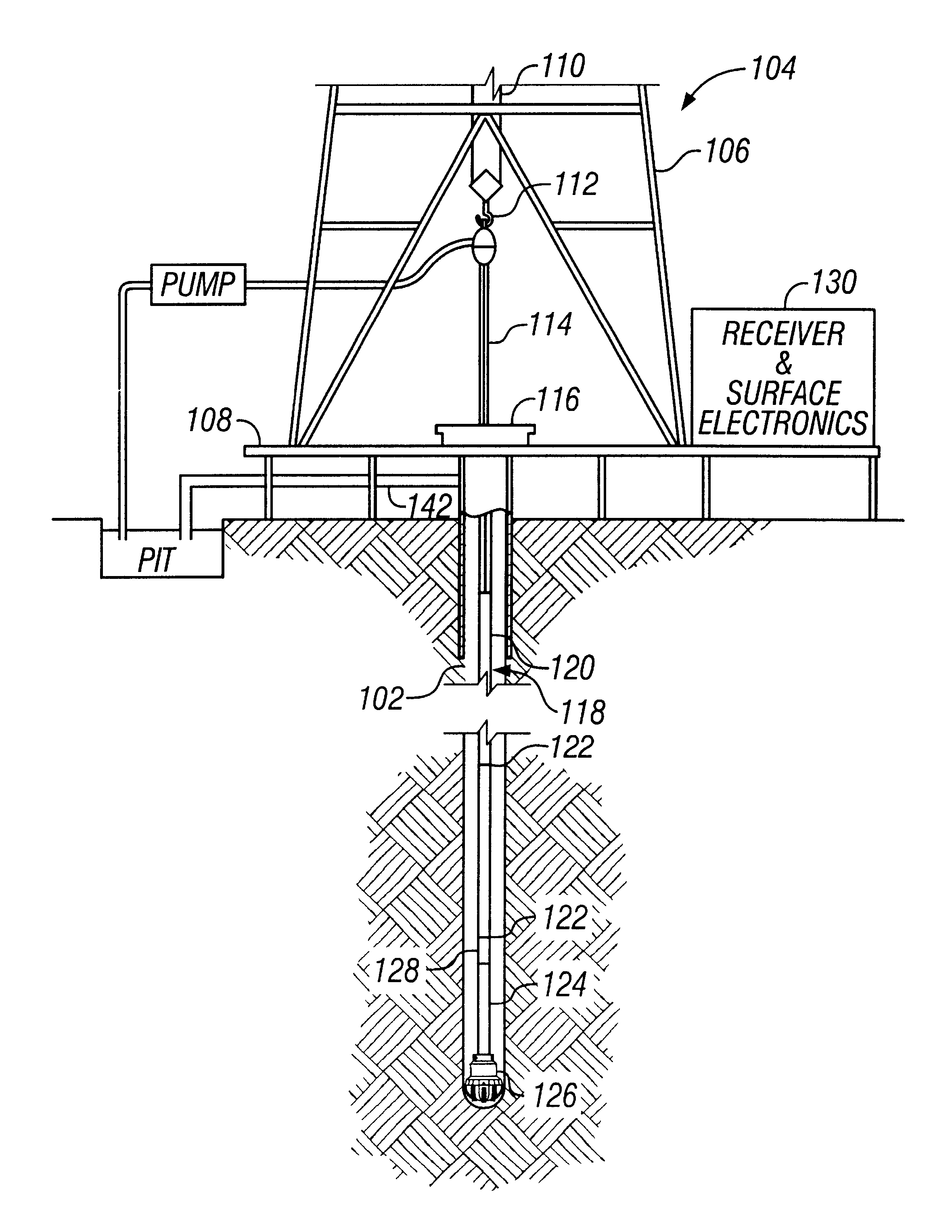
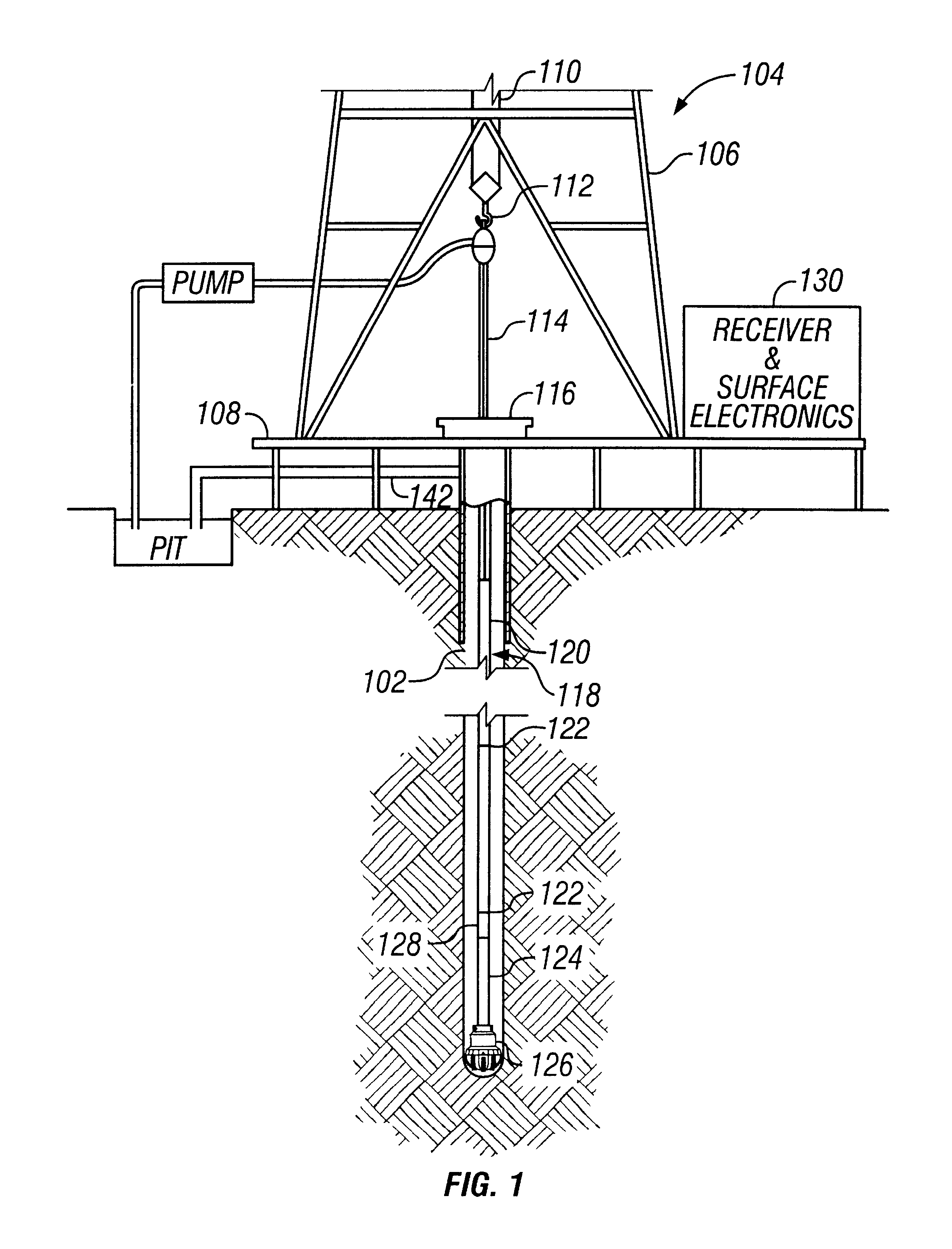
FIG. 1 is an elevation view of a simultaneous drilling and logging system that may be used in a preferred method according to the present invention. A well borehole 102 is drilled into the earth under control of surface equipment including a rotary drilling rig 104. In accordance with a conventional arrangement, the rig 104 includes a derrick 106, a derrick floor 108, draw works 110, a hook 112, a kelly joint 114, a rotary table 116, and drill string 118. The drill string 118 includes drill pipe 120 secured to the lower end of kelly joint 114 and to the upper end of a section comprising a plurality of pipes joined in a conventional manner such as threaded pipe joints (“collars”) 122. A bottom hole assembly (BHA) 124 is shown located down hole on the drill string 118 near a drill bit 126.

The BHA 124 carries various sensors (not separately shown) for measuring formation and drilling parameters. An acoustic transmitter 128 may be carried by the BHA 124 or above the BHA 124. The transmi...


PUM


Abstract

The present invention is a method of transmitting one or more acoustic signals in a drill string using PSK, ASK, FSK or MSFK. The method includes determining one or more stopbands and one or more passbands by testing or modeling the drill string. Two modulating frequencies are selected that are equidistant about a carrier frequency, and which are located within at least one passband. Data representative of downhole measurements or calculations are converted to signals to be transmitted at the modulating frequencies.

Description

BACKGROUND OF THE INVENTION1. Field of the InventionThis invention relates generally to signal transmission methods, and more particularly to acoustic data telemetry methods for transmitting data from a downhole location to the surface.2. Description of the Related ArtTo obtain hydrocarbons such as oil and gas, boreholes are drilled by rotating a drill bit attached at a drill string end. Modern directional drilling systems generally employ a drill string having a bottomhole assembly (BHA) and a drill bit at end thereof that is rotated by a drill motor (mud motor) and / or the drill string. A number of downhole devices in the BHA measure certain downhole operating parameters associated with the drill string and the wellbore. Such devices typically include sensors for measuring downhole temperature, pressure, tool azimuth, tool inclination, drill bit rotation, weight on bit, drilling torque, etc. Downhole instruments, known as measurement-while-drilling (“MWD”) and logging-while-drillin...

Claims


Application Information

Patent Timeline
IPC IPC(8): E21B47/16E21B47/12
CPCE21B47/16
Inventor MACPHERSON, JOHN D.
Owner BAKER HUGHES INC
Features
  • R&D
  • Intellectual Property
  • Life Sciences
  • Materials
  • Tech Scout
  • Unparalleled Data Quality
  • Higher Quality Content
  • 60% Fewer Hallucinations
Learn More